Select Mesh Elements#
Functionality#
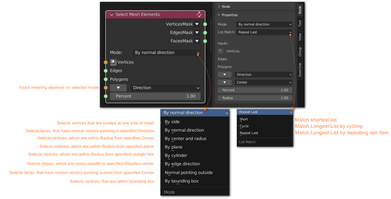
This node allows to select mesh elements (vertices, edges and faces) by their geometrical location, by one of supported criteria.
You can combine different criteria by applying several instances of this node and combining masks with Logic node.
Inputs#
This node has the following inputs:
Vertices
Edges
Faces
Direction. Direction vector. Used in modes: By side, By normal, By plane, By cylinder. Exact meaning depends on selected mode.
Center. Center or base point. Used in modes: By sphere, By plane, By cylinder, By bounding box.
Percent. How many vertices to select. Used in modes: By side, By normal.
Radius. Allowed distance from center, or line, or plane, to selected vertices. Used in modes: By sphere, By plane, By cylinder, By bounding box.
Parameters#
This node has the following parameters:
Mode. Criteria type to apply. Supported criteria are:
By side. Selects vertices that are located at one side of mesh. The side is specified by Direction input. So you can select “rightmost” vertices by passing (0, 0, 1) as Direction. Number of vertices to select is controlled by Percent input: 1% means select only “most rightmost” vertices, 99% means select “all but most leftmost”. More exactly, this mode selects vertex V if (Direction, V) >= max - Percent * (max - min), where max and min are maximum and minimum values of that scalar product amongst all vertices.
By normal direction. Selects faces, that have normal vectors pointing in specified Direction. So you can select “faces looking to right”. Number of faces to select is controlled by Percent input, similar to By side mode. More exactly, this mode selects face F if (Direction, Normal(F)) >= max - Percent * (max - min), where max and min are maximum and minimum values of that scalar product amongst all vertices.
By center and radius. Selects vertices, which are within Radius from specified Center; in other words, it selects vertices that are located inside given sphere. More exactly, this mode selects vertex V if Distance(V, Center) <= Radius. This mode also supports passing many points to Center input; in this case, “Distance” is distance from vertex to the nearest “Center”.
By plane. Selects vertices, which are within Radius from specified plane. Plane is specified by providing normal vector (Direction input) and a point, belonging to that plane (Center input). For example, if you specify Direction = (0, 0, 1) and Center = (0, 0, 0), the plane will by OXY. More exactly, this mode selects vertex V if Distance(V, Plane) <= Radius.
By cylinder. Selects vertices, which are within Radius from specified straight line. Line is specified by providing directing vector (Direction input) and a point, belonging to that line (Center input). For example, if you specify Direction = (0, 0, 1) and Center = (0, 0, 0), the line will by Z axis. More exactly, this mode selects vertex V if Distance(V, Line) <= Radius.
By edge direction. Selects edges, which are nearly parallel to specified Direction vector. Note that this mode considers edges as non-directed; as a result, you can change sign of all coordinates of Direction and it will not affect output. More exactly, this mode selects edge E if Abs(Cos(Angle(E, Direction))) >= max - Percent * (max - min), where max and min are maximum and minimum values of that cosine.
Normal pointing outside. Selects faces, that have normal vectors pointing outside from specified Center. So you can select “faces looking outside”. Number of faces to select is controlled by Percent input. More exactly, this mode selects face F if Angle(Center(F) - Center, Normal(F)) >= max - Percent * (max - min), where max and min are maximum and minimum values of that angle.
By bounding box. Selects vertices, that are within bounding box defined by points passed into Center input. Radius is interpreted as tolerance limit. For examples:
If one point (0, 0, 0) is passed, and Radius = 1, then the node will select all vertices that have -1 <= X <= 1, -1 <= Y <= 1, -1 <= Z <= 1.
If points (0, 0, 0), (1, 2, 3) are passed, and Radius = 0.5, then the node will select all vertices that have -0.5 <= X <= 1.5, -0.5 <= Y <= 2.5, -0.5 <= Z <= 3.5.
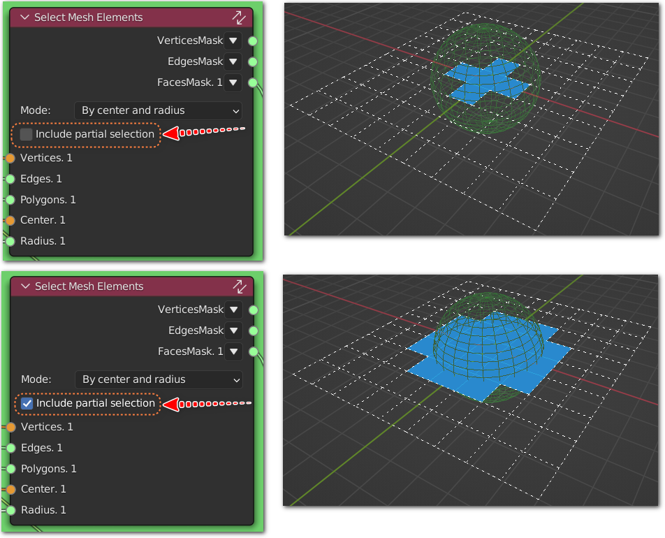
Include partial selection. Not available in By normal mode. All other modes select vertices first. This parameter controls either we need to select edges and faces that have any of vertices selected (Include partial = True), or only edges and faces that have all vertices selected (Include partial = False).
Level. Data nesting level to work with. Default (and minimum) value is 2, which means that the node’s Vertices input will expect a list of lists of vertices, and the node will output list of lists of booleans; i.e. node will process a list of meshes, as most of nodes usually do. With Level of 3, the node will expect a list of lists of meshes, and output a list of lists of lists of booleans; and so on.
Outputs#
This node has the following outputs:
VerticesMask. Mask for selected vertices.
EdgesMask. Mask for selected edges. Please note that this mask relates to list of vertices provided at node input, not list of vertices selected by this node.
FacesMask. Mask for selected faces. Please note that this mask relates to list of vertices provided at node input, not list of vertices selected by this node.
Mode - By Side#
Selects vertices that are located at one side of mesh. The side is specified by Direction input. So you can select “rightmost” vertices by passing (0, 0, 1) as Direction. Number of vertices to select is controlled by Percent input: 1% means select only “most rightmost” vertices, 99% means select “all but most leftmost”. More exactly, this mode selects vertex V if (Direction, V) >= max - Percent * (max - min), where max and min are maximum and minimum values of that scalar product amongst all vertices.
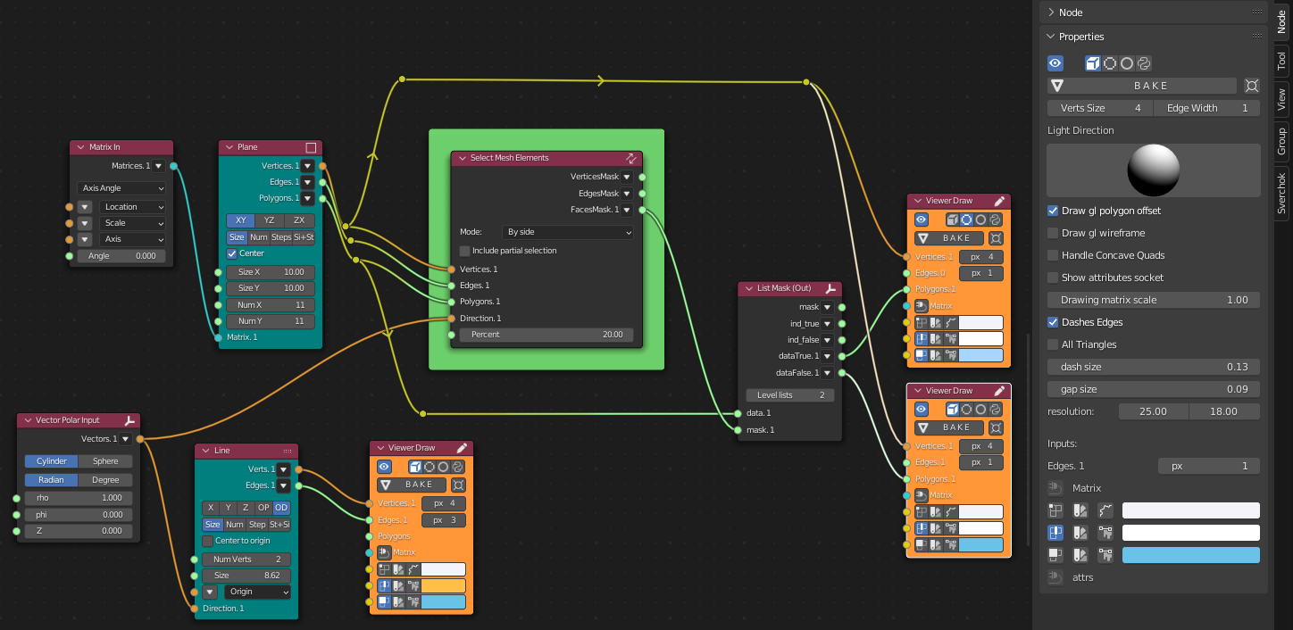
Generator-> Line
Generator-> Plane
Vector-> Vector Polar Input
Matrix-> Matrix In
List-> List Mask (Out)
Viz-> Viewer Draw
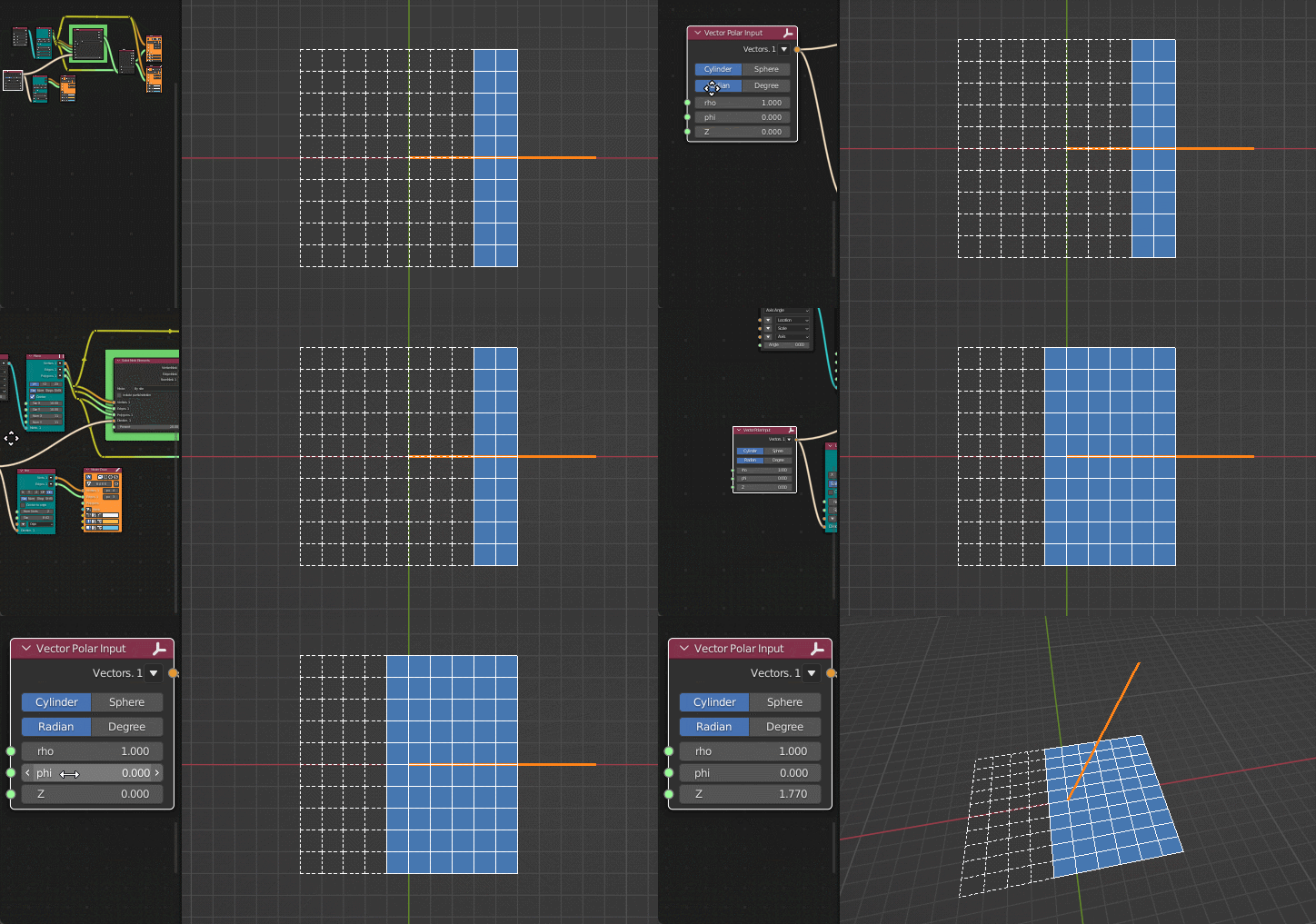
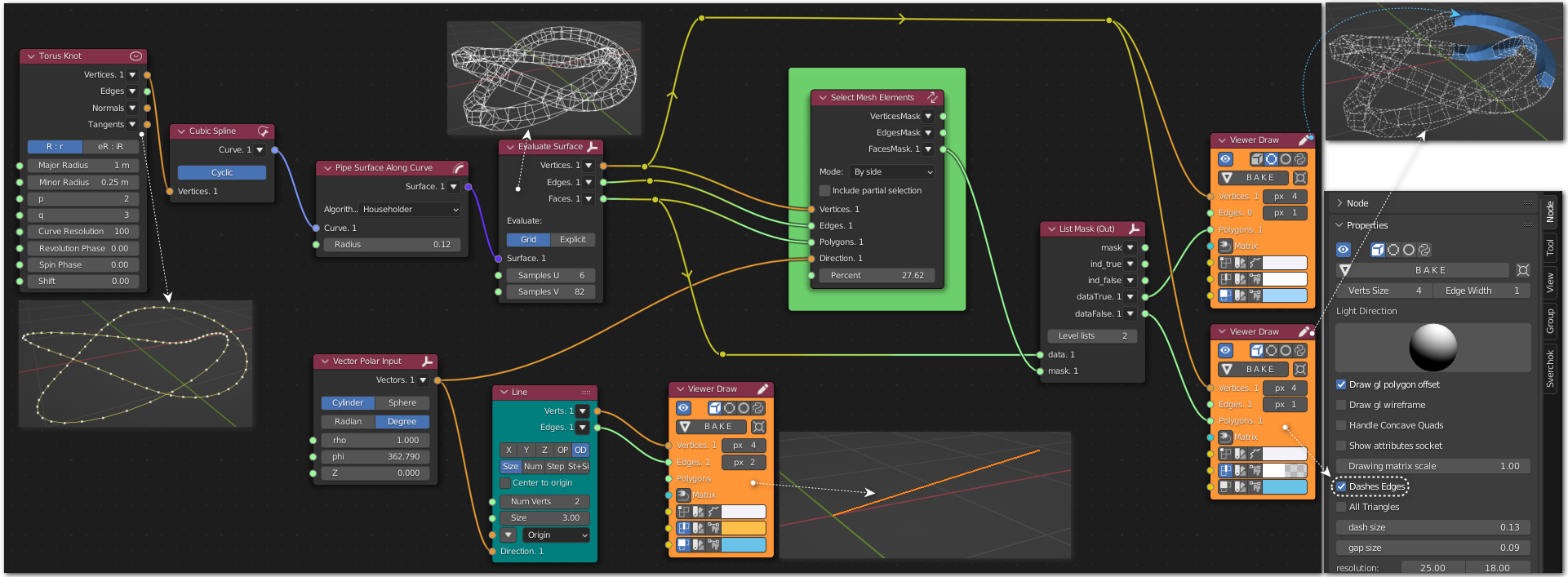
Generator-> Line
Generator->Generators Extended Torus Knot
Curves-> Cubic Spline
Surfaces-> Pipe Surface Along Curve
Surfaces-> Evaluate Surface
Vector-> Vector Polar Input
List-> List Mask (Out)
Viz-> Viewer Draw
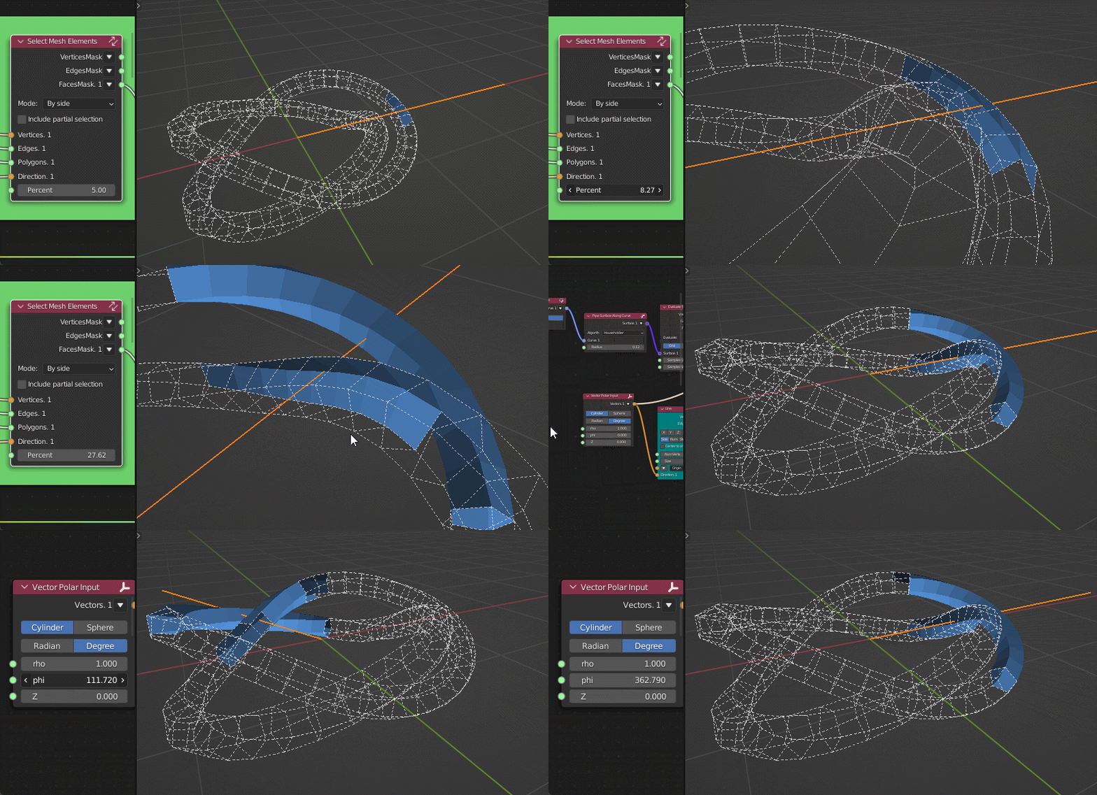
Mode - By Normal Direction#
Selects faces, that have normal vectors pointing in specified Direction. So you can select “faces looking to right”. Number of faces to select is controlled by Percent input, similar to By side mode. More exactly, this mode selects face F if (Direction, Normal(F)) >= max - Percent * (max - min), where max and min are maximum and minimum values of that scalar product amongst all vertices.
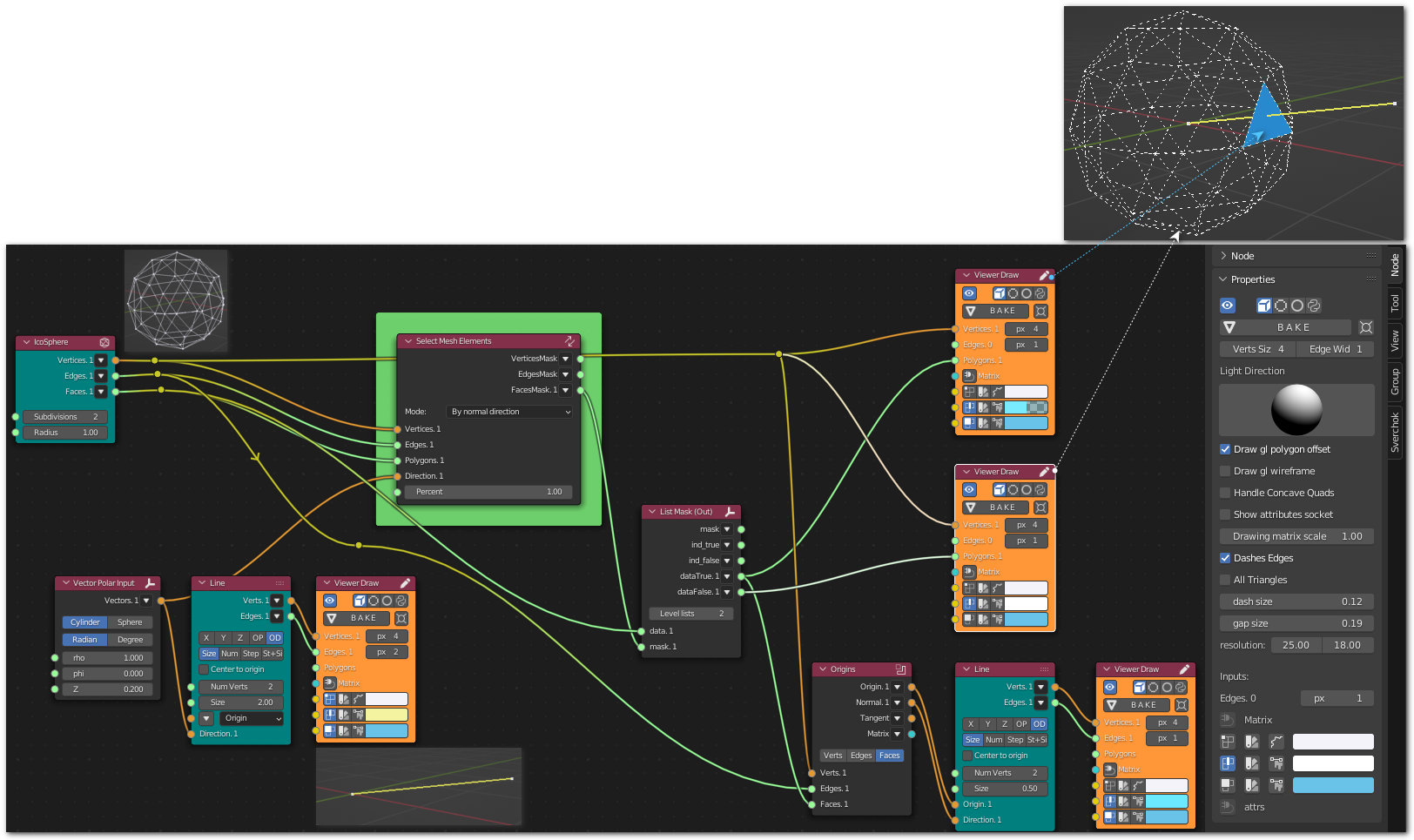
Generator-> Line
Generator-> IcoSphere
Analyzers-> Origins
Vector-> Vector Polar Input
List-> List Mask (Out)
Viz-> Viewer Draw
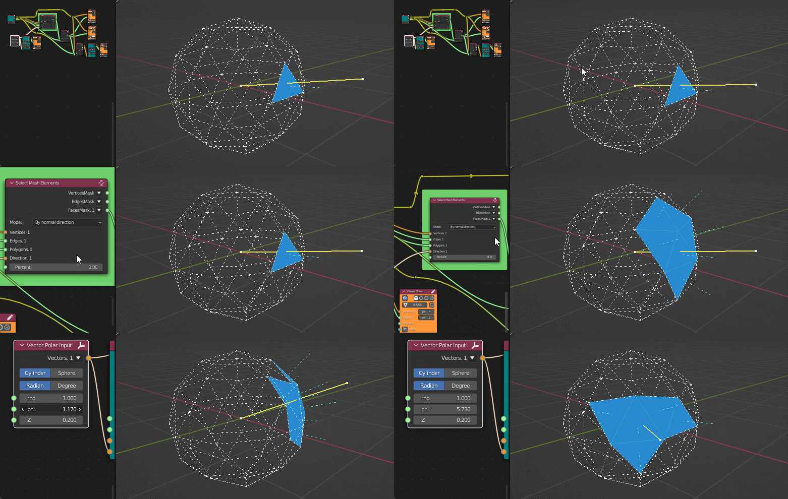
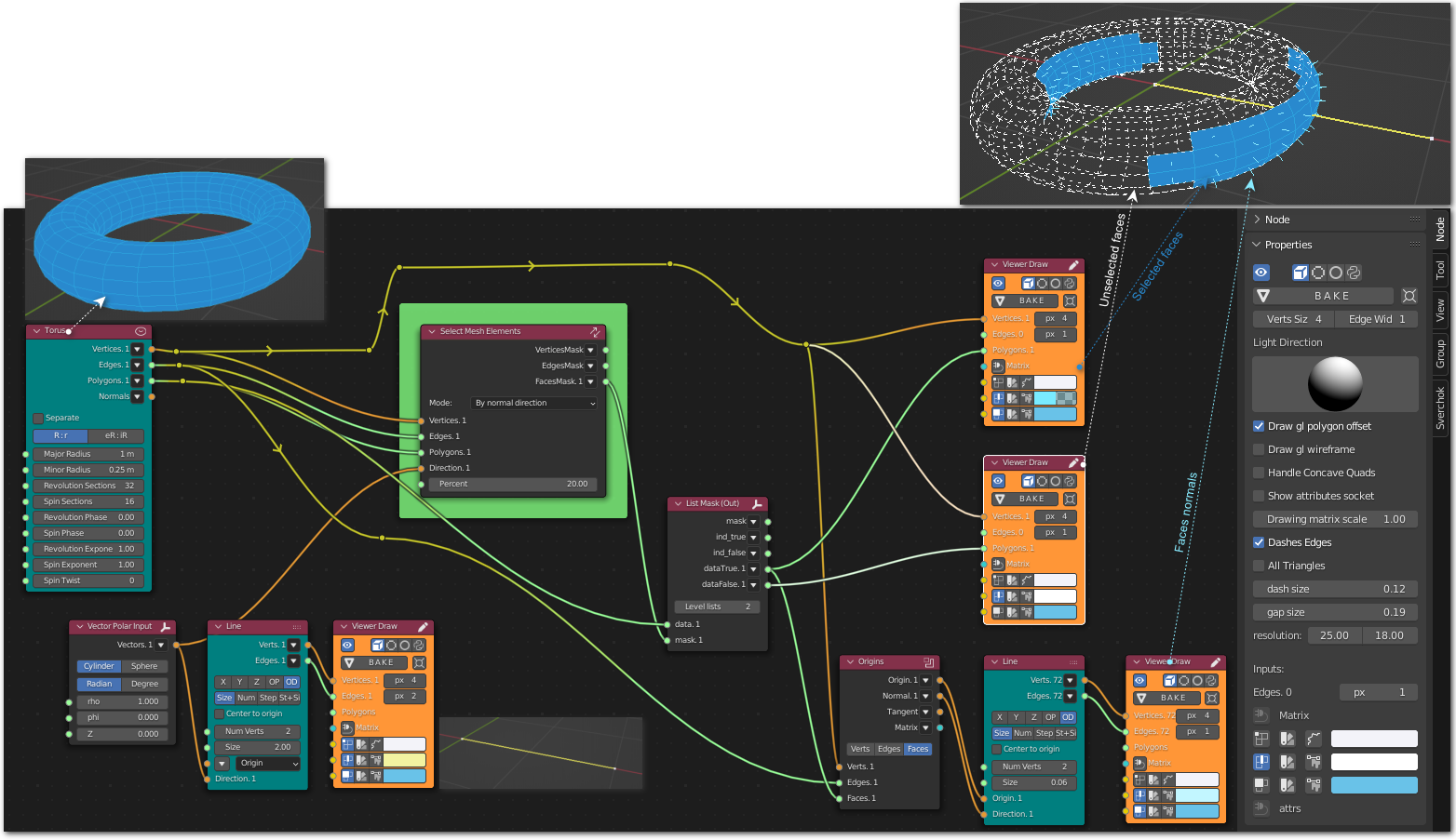
Generator-> Line
Generator-> Torus
Analyzers-> Origins
Vector-> Vector Polar Input
List-> List Mask (Out)
Viz-> Viewer Draw

Mode - By Center and Radius#
Selects vertices, which are within Radius from specified Center; in other words, it selects vertices that are located inside given sphere. More exactly, this mode selects vertex V if Distance(V, Center) <= Radius. This mode also supports passing many points to Center input; in this case, “Distance” is distance from vertex to the nearest “Center”.
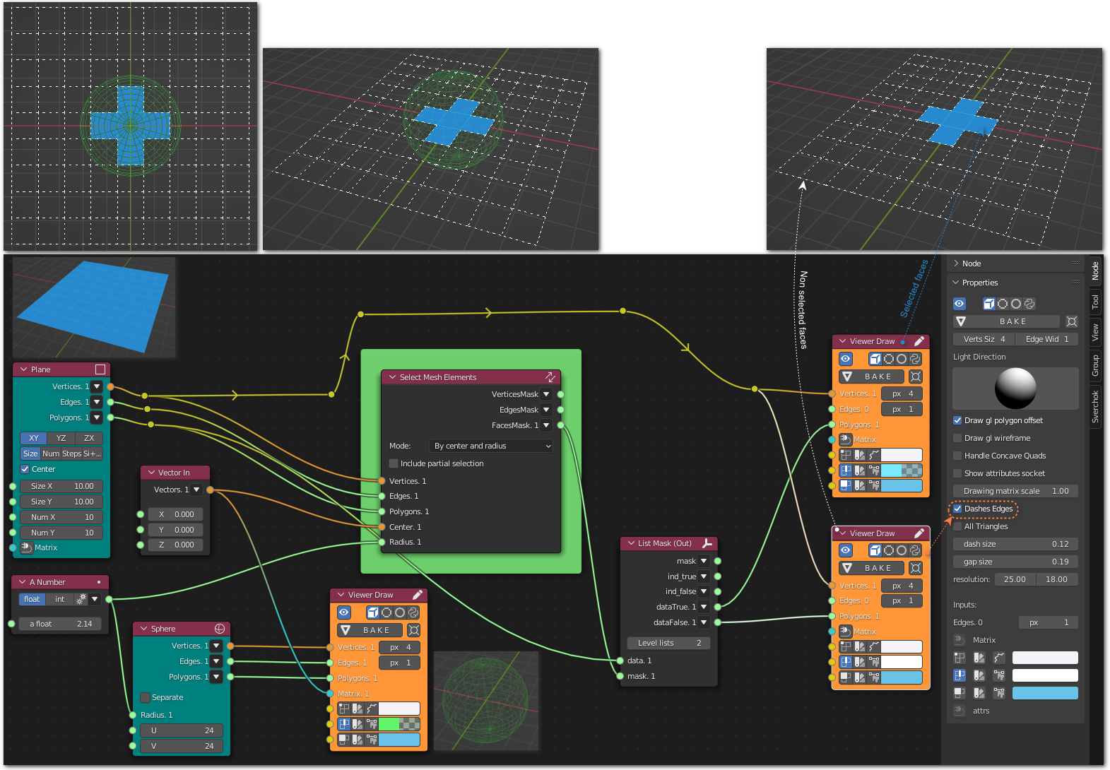
Generator-> Plane
Generator-> Sphere
Number-> A Number
Vector-> Vector In
List-> List Mask (Out)
Viz-> Viewer Draw
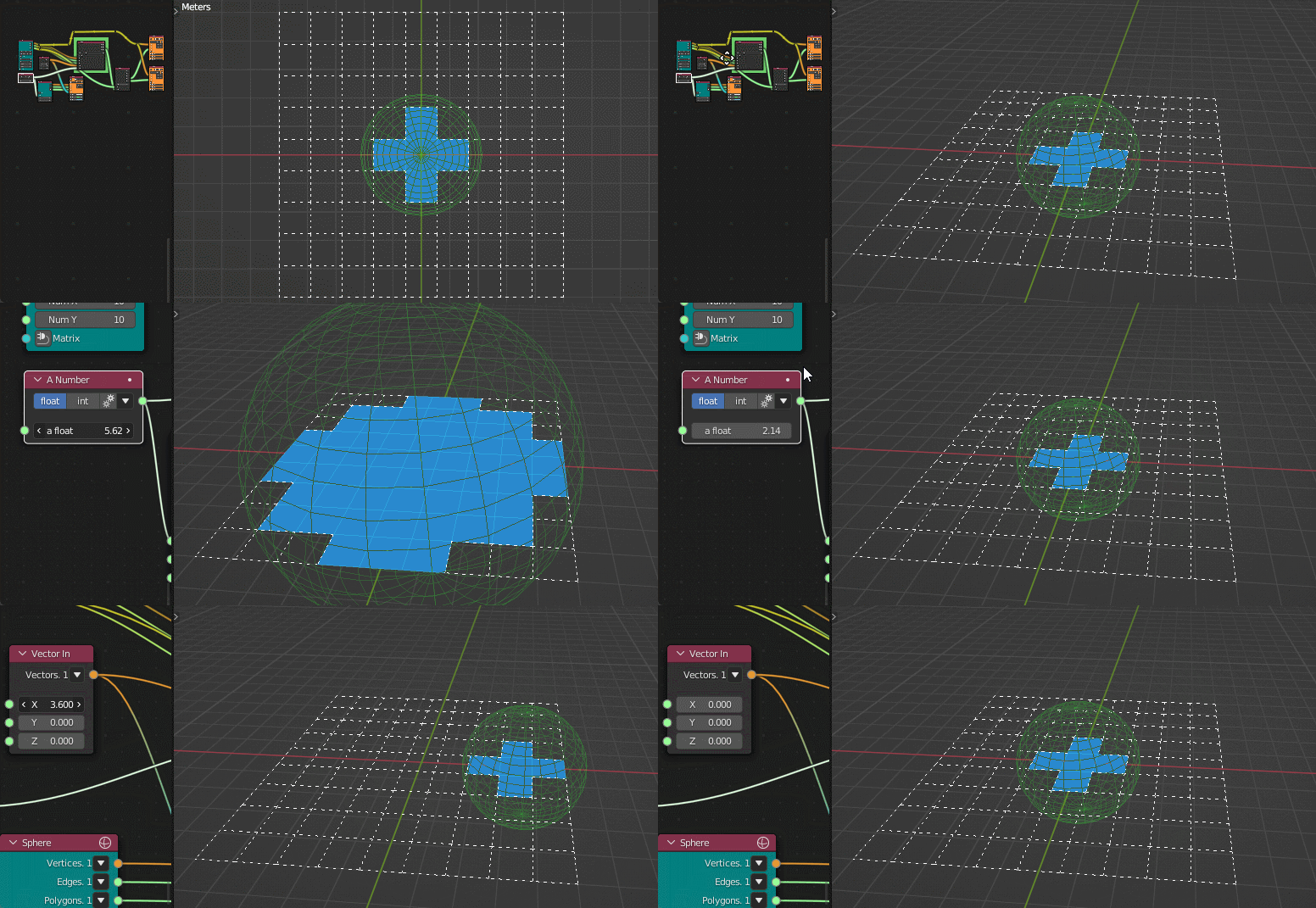
Mode - By Plane#
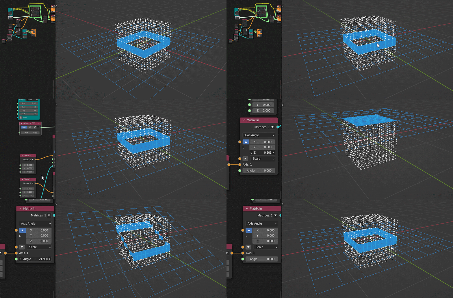
Selects vertices, which are within Radius from specified plane. Plane is specified by providing normal vector (Direction input) and a point, belonging to that plane (Center input). For example, if you specify Direction = (0, 0, 1) and Center = (0, 0, 0), the plane will by OXY. More exactly, this mode selects vertex V if Distance(V, Plane) <= Radius.
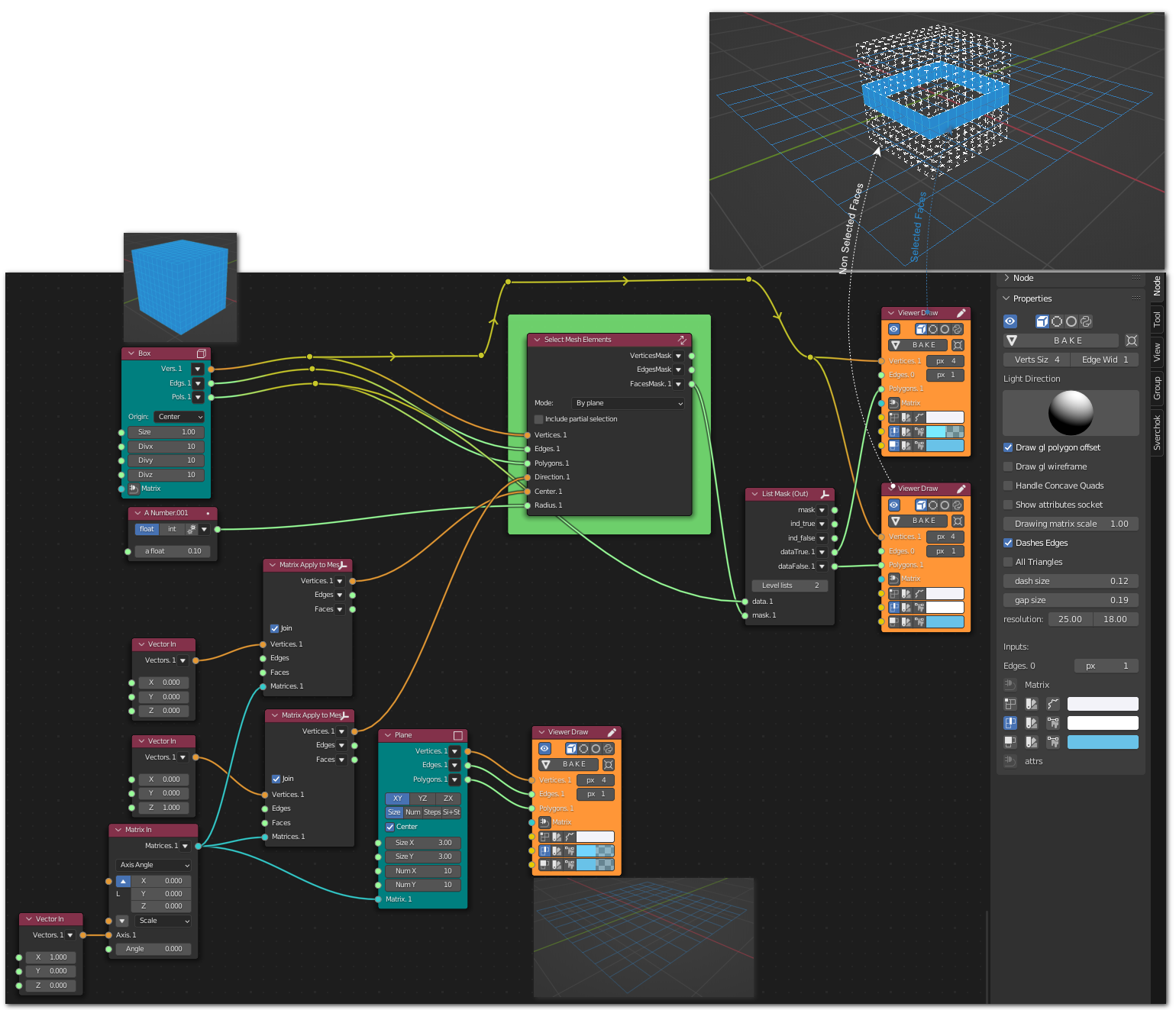
Generator-> Plane
Generator-> Box
Number-> A Number
Vector-> Vector In
Matrix-> Matrix Apply to Mesh
List-> List Mask (Out)
Viz-> Viewer Draw
Mode - By Cylinder#
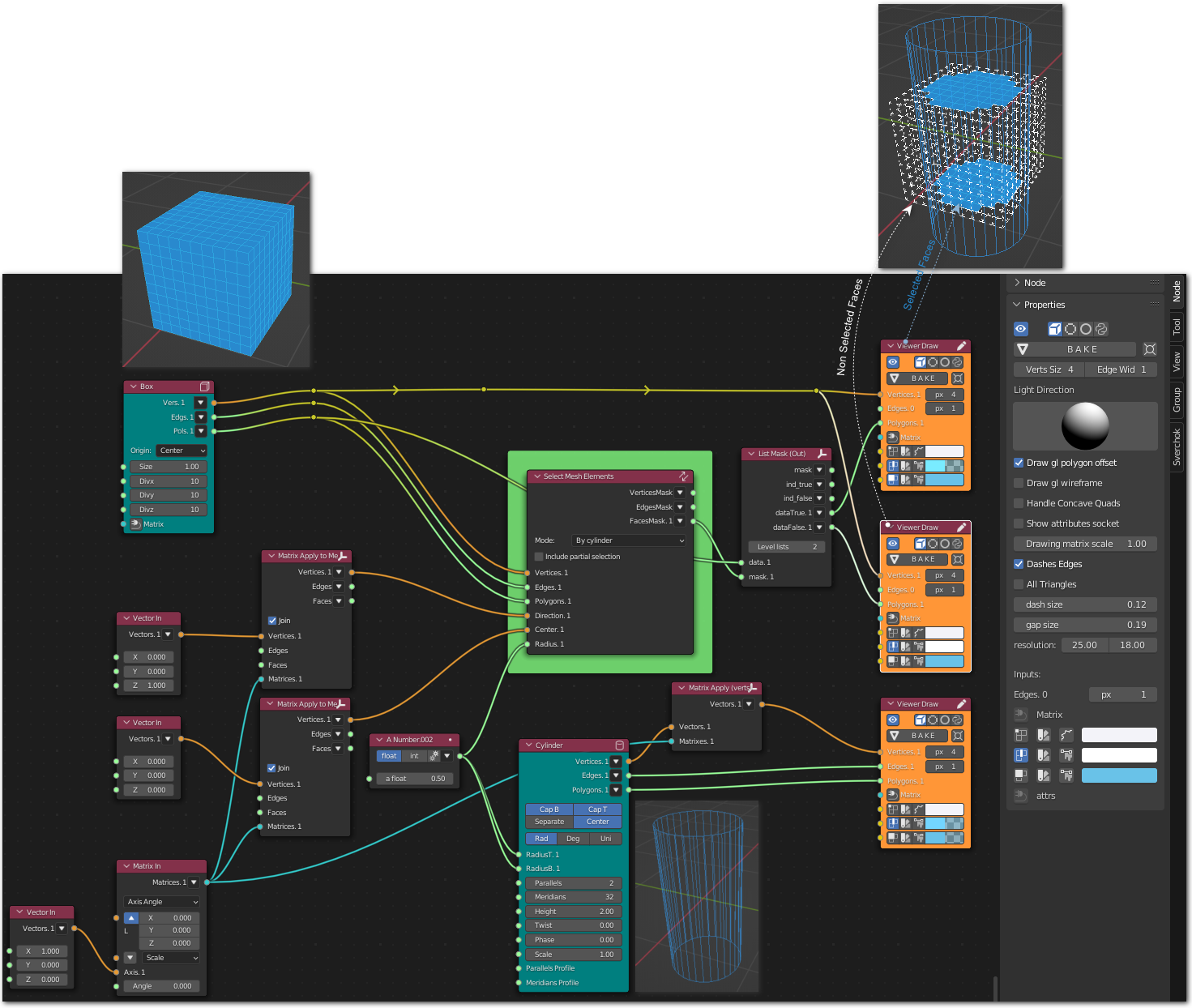
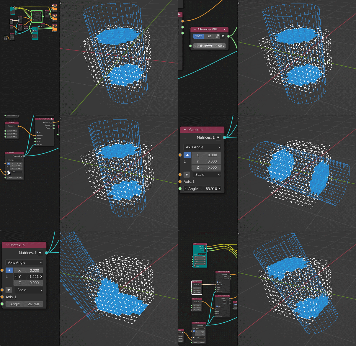
Selects vertices, which are within Radius from specified straight line. Line is specified by providing directing vector (Direction input) and a point, belonging to that line (Center input). For example, if you specify Direction = (0, 0, 1) and Center = (0, 0, 0), the line will by Z axis. More exactly, this mode selects vertex V if Distance(V, Line) <= Radius.
Generator-> Box
Generator-> Cylinder
Transform-> Matrix Apply (verts)
Number-> A Number
Vector-> Vector In
Matrix-> Matrix In
Matrix-> Matrix Apply to Mesh
List-> List Mask (Out)
Viz-> Viewer Draw
Mode - By Edge Direction#
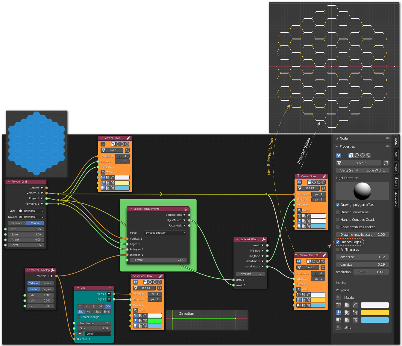
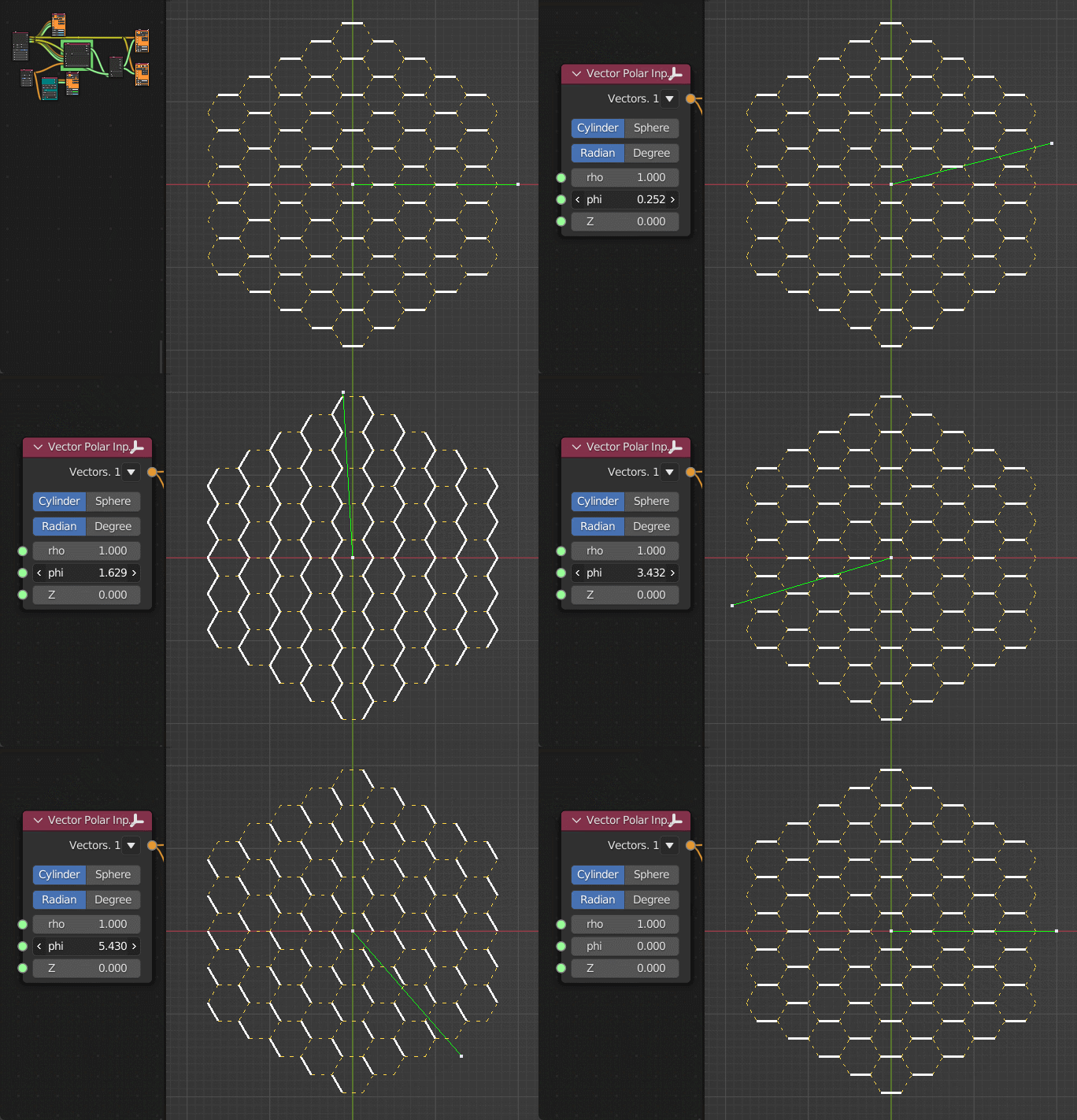
Selects edges, which are nearly parallel to specified Direction vector. Note that this mode considers edges as non-directed; as a result, you can change sign of all coordinates of Direction and it will not affect output. More exactly, this mode selects edge E if Abs(Cos(Angle(E, Direction))) >= max - Percent * (max - min), where max and min are maximum and minimum values of that cosine.
Generator-> Line
Generator->Generator Extended-> Polygon Grid
Vector-> Vector Polar Input
List-> List Mask (Out)
Viz-> Viewer Draw
Mode - By Bounding Box#
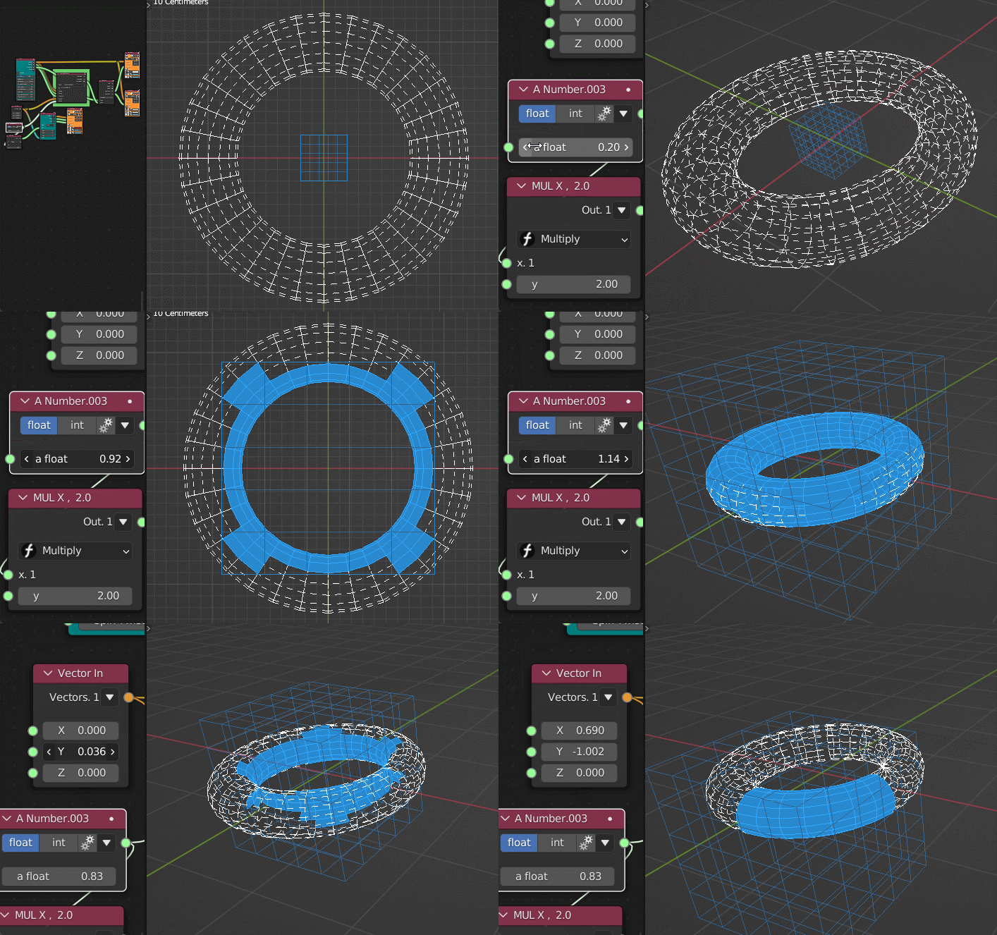
Selects vertices, that are within bounding box defined by points passed into Center input. Radius is interpreted as tolerance limit.
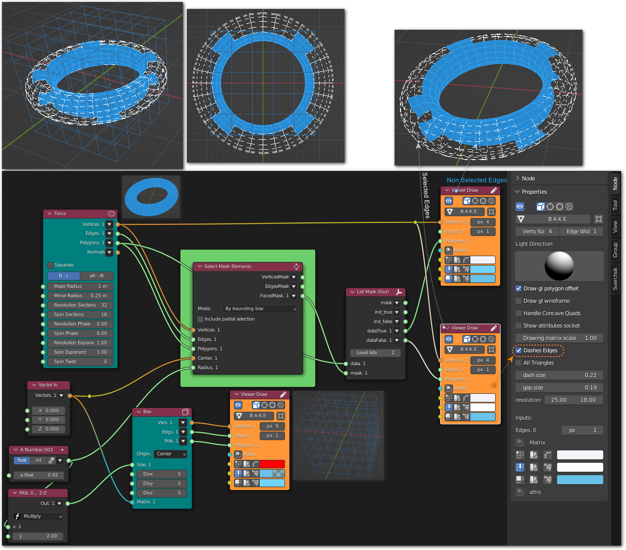
Generator-> Box
Generator-> Torus
Number-> A Number
MUL: Number-> Scalar Math
Vector-> Vector In
List-> List Mask (Out)
Viz-> Viewer Draw
Examples of usage#
Select rightmost vertices:

Select faces looking to right:

Select vertices within sphere:

Using multiple centers:
See also: Analyzers-> KDT Closest Verts

Select vertices near OYZ plane:

Select vertices near vertical line:

Bevel only edges that are parallel to Z axis:

Select faces that are looking outside:

Select faces by bounding box:
