Viewer Draw#
Functionality#
aliases: vdmk4, viewer draw 4
This node takes your geometry and displays it in the 3d view, using opengl and shaders. The node is intended to be a fast way to show you the result of your node tree. We’ve added various levels of refinements that you may find useful to better understand the virtual geometry you’ve created.
Shader modes#
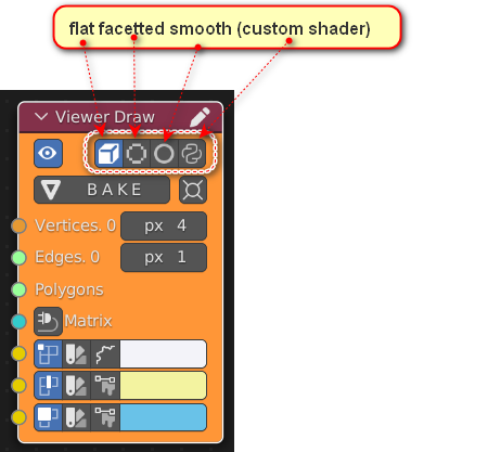
flat
You can view your geometry as a single flat colour, this requires little to no processing before being passed onto the shader and is lightning fast. This is useful when you are working with large quantities of polygons.
facetted
This mode calculates the face normal and angle to a light source, and uses the result to colour the face some shade of the color you set from the UI. This is not a hugely calculation intensive mode, all this data is produced once per update, and reused if you rotate around the viewport. It is only recalculated if the geometry input is changed / or the node is told to reprocess.
smooth
The same calculations are performed as in facetted mode, but instead of each face (triangle) being colored uniformly, each face’s vertices get a color associated with the vertex normal. This is as close as we will get to smooth shading, at low processing cost.
custom shader
If this interests you, you should read the node’s source code, and check out the development thread for examples. This is the more experimental part of the node and subject to changing eventually. At present this lets you load a VertexShader and FragmentShader from the bpy.data.texts block.
Face Culling#
Blender: https://docs.blender.org/api/current/gpu.state.html#gpu.state.face_culling_set
wiki: https://wikis.khronos.org/opengl/Face_Culling
Visible only for Blender 3.5 and more. Used only in Blender 3D Viewport. Has no influence for render or baking mesh, edges or vertices.
None - default. Show all faces
Front - hide front faces
Back - hide back faces
Features#
You can view Verts on their own, and set their size and color. Color can be set by vertex or by object, also can generate random colors in one click.
You can view Edges, set their color and thickness and even apply a configurable Dashed edge style. Color can be set by edge or by object, also can use vertex colors to color edges.
You can view Faces, set their color, and infer the associated Edges. The non-flat shader modes require Faces to produce enough information for normals. Color can be set by polygon or by mesh, also can use vertex colors to color edges.
Bake the current mesh(es)
Set the 3d cursor to the center of Mesh 1. (handy for rotating around in this virtual geometry)
“Polygon offset” (to prevent z-fighting between edges and faces), on by default.
“quad tessellator”, this mode treats all faces as potentially irregular and uses extended mathutils to get the normal.
can show matrices if you only connect matrices without any other geometry. Size can be defined in the N-Panel or in the right click menu
alpha channel, the color socket is rgba. - multiple simultaneous viewers mixing opaque geometry may show render artifacts.
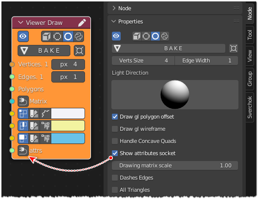
(experimental..) the “Attribute socket” can be used to configure the viewer node from another node, in this case a dedicated Attributes node.
Inputs#
Vertices
Edges
Faces
Matrix
Vertices color
Edges color
Faces color
attrs: Attributes socket
Examples#
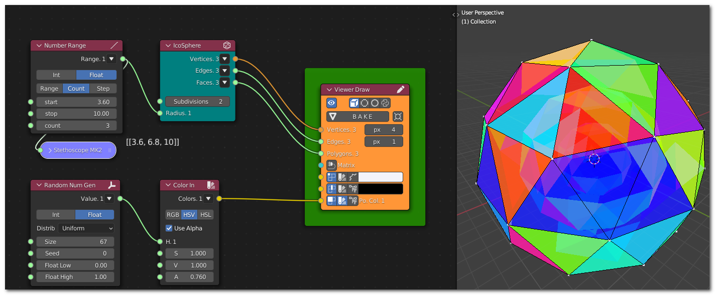
Generator-> IcoSphere
Number-> Number Range
Color-> Color In
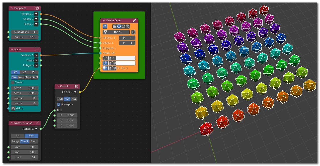
Generator-> IcoSphere
Generator-> Plane
Number-> Number Range
Color-> Color In
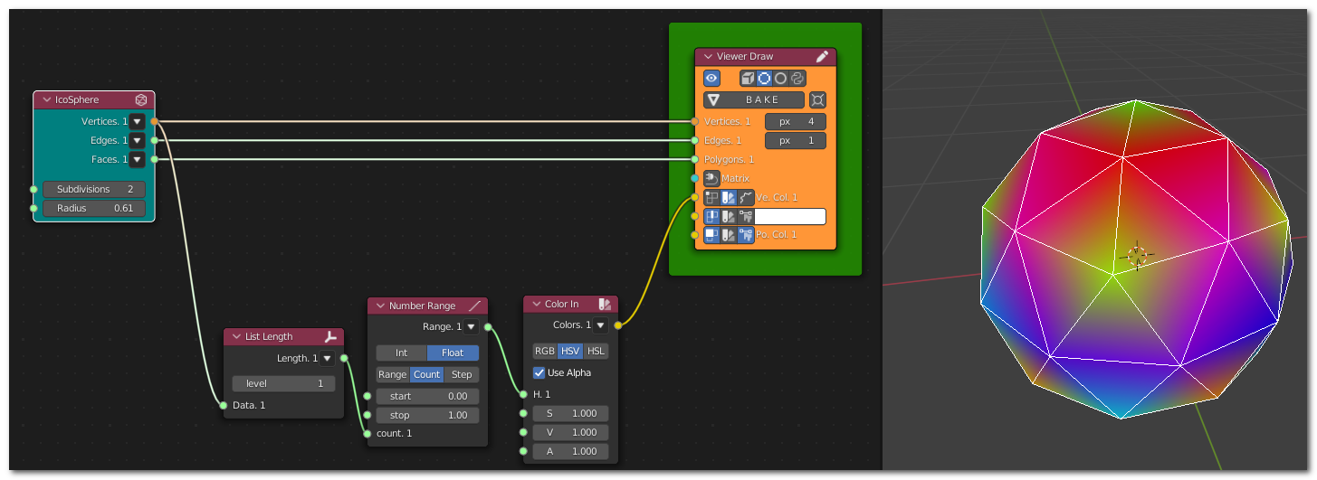
Generator-> IcoSphere
List->List Main-> List Length
Number-> Number Range
Color-> Color In
Extra params:

Generator-> IcoSphere
Generator-> Line
Analyzers-> Component Analyzer
Support#
it’s relatively stable, it’s been in development on and off for a year, since the first 2.8 releases. But, you will find bugs, let us know. Better yet, suggest fixes (preferably not requiring dedicated hardware) :)