Plane#


Functionality#
Plane generator creates a grid in the plane XY/YZ or ZX, the node offers different methods to define the size of the grid and the spacing between the points.
Size Mode: the planar grid is defined by its total size and the number of vertices in both axis Number: the planar grid is defined by the spacing of the vertices and the number of them Steps: this mode expects a list with spacing between the vertices, it can support variable spacing Size + Steps: similar to the Steps mode but normalizes the list to fit a defined size
Inputs and Parameters#
All parameters except Direction, Center can be given by the node or an external input.
Param |
Type |
Default |
Description |
|---|---|---|---|
Size X |
Float |
2 |
number of vertices in X. The minimum is 2. |
Size Y |
Float |
2 |
number of vertices in X. The minimum is 2. |
N Verts X |
Int |
2 |
number of vertices in X. The minimum is 2. |
N Verts Y |
Int |
2 |
number of vertices in X. The minimum is 2. |
Step X |
Float |
1.00 |
length between vertices in X axis |
Step Y |
Float |
1.00 |
length between vertices in Y axis |
Direction |
Enum |
XY |
generate grid in XY, YZ or ZX plane |
Center |
Boolean |
False |
center the plane around origin |
Matrix |
Matrix |
None |
position, scale and rotation of the plane |
Advanced Parameters#
In the N-Panel (and on the right-click menu) you can find:
- Simplify Output: Method to keep output data suitable for most of the rest of the Sverchok nodes
None: Do not perform any change on the data. Only for advanced users
Join: The node will join the deepest level of planes in one object
Flat: It will flat the output to keep the one grid per object
Match List Global: Define how list with different lengths should be matched. Refers to the matching of groups (level 1)
Match List Local: Define how list with different lengths should be matched. Refers to the matching inside groups (level 2)
Output NumPy: Get NumPy arrays in stead of regular lists (makes the node faster). Available for Vertices, Edges and Polygons
Outputs#
Vertices, Edges and Polygons. All outputs will be generated. Depending on the type of the inputs, the node will generate only one or multiples independent grids.
Example of usage#


Number-> List Input
Viz-> Viewer Draw
Text-> Stethoscope
Generating the same grid with different modes:

Viz-> Viewer Draw
Matrix-> Matrix In
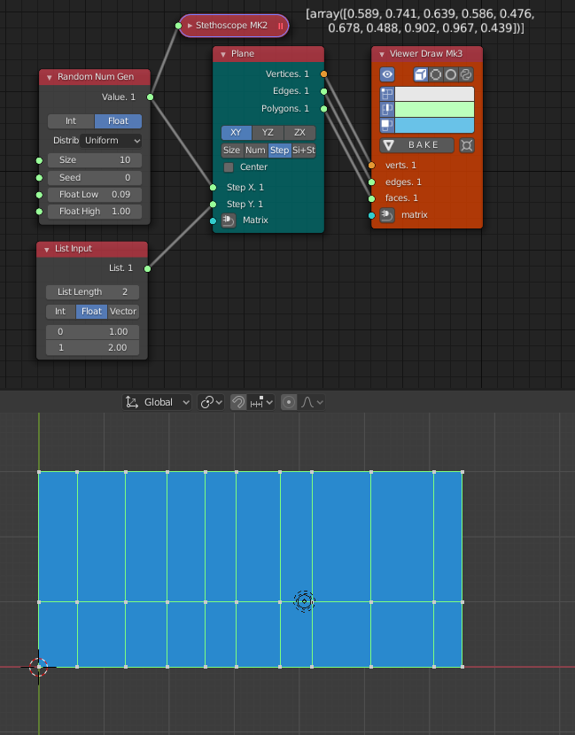
Using the ‘Steps’ mode to control the grid spacing

Number-> Random Num Gen
Number-> List Input
Viz-> Viewer Draw
Text-> Stethoscope
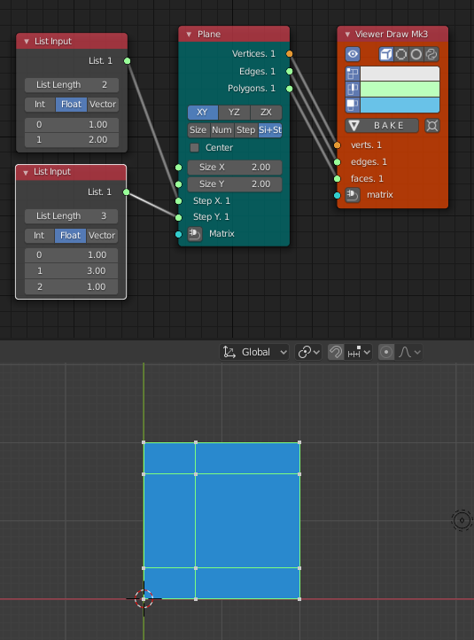
In the ‘Si + St’ mode (Size + Steps) the step list is used to control the proportion of the spacing between Vertices

Number-> List Input
Viz-> Viewer Draw
With the list matching in ‘cycle’ advanced rhythms can be achieved.

Number-> Number Range
List->List Struct-> List Split
Text-> Stethoscope
Viz-> Viewer Draw
The matrix input is be vectorized and accepts many lists of matrixes, note in this example that the ‘Flat Output’ of the ‘Matrix In’ node is un-checked.

Generator-> Line
Number-> List Input
Number-> Number Range
Matrix-> Matrix In
Viz-> Viewer Draw
The first ‘Line’ node generates one line with two verts.
The second ‘Line’ node generates two lines with five verts.
The ‘Matrix In’ node generates two list with five matrix in each list
The Plane node will match the first matrix list with the first value of the ‘List input’ node (two vert per direction) and the second matrix list with the second value of the ‘List Input’ node.