
NURBS Birail#
Dependencies#
This node can optionally use Geomdl library; it can also optionally use FreeCAD libraries.
Functionality#
This node generates a NURBS Surface object by sweeping one NURBS curve (called “profile”) along two other NURBS curves (called paths or rails), so that the starting point of the profile goes along the first path, and the ending point of the profile goes along the second path.
Several profile curves can be also used; in this case the resulting surface will be interpolated between them. If several profile curves are used, the user can provide specific values of path’s curve T parameter, at which profile curves must be placed; otherwise, the node will place them automatically evenly along T parameter of the path curve.
By default it is supposed that initially the provided profile curve(s) lie in XOY plane. However, there is an option to instruct the node to try to figure out correct rotation of profile curve(s). Note that this option may result in precision loss in some cases. Or, in other cases, it can guess desired profile rotation incorrectly. In such cases, you will have to place your profile curves in XOY plane and disable “Auto rotate” flag.
The node works by placing several copies of profile curve along the path curves. If several profile curves are used, then the node interpolates between them and places these interpolated curves along the path curve. Then one of algorithms can be used:
Lofting (legacy). A loft surface is generated from profile curves placed along path curves.
Gordon. Gordon surface is generated from path curves and profile curves. See documentation of “Surface from NURBS curves net” node for more information.
Tensor Product. This algorithm is based on the idea that control points of the birail surface can be calculated as tensor product of path curve control points and profile curve control points. Surface weights are calculated from weights of profile curve, by using interpolation between corresponding weights of path curves.
Different algorithms have different strengths:
Characteristic |
Lofting |
Gordon Surface |
Tensor Product |
|---|---|---|---|
Follows path curves |
Approximately |
Exactly |
Exactly |
Support for rational curves |
Yes |
No |
Yes |
Allows to control parametrization |
Yes |
Yes |
No |
Number of generated control points |
M * VSections |
May be much more, depends on parmetrization |
M * N |
Performance |
Relatively fast |
Relatively slow |
Relatively fast |
Loft algorithm works faster compared to Gordon Surface algorithm with the same number of profile curve copies (VSections parameter). But, in order for resulting surface to touch path curves precisely enough, you usually will have to use high enough value of VSections parameter.
Gordon algorithm produces the surface which always touches path curves precisely, even with small number of V sections. But Gordon algorithm is slower, and it produces surfaces with more control points. Also, Gordon algorithm does not support (yet) rational curves. One can either use Loft algorithm for such curves, or pass curves through “Curve to NURBS” node to make them non-rational.
Tensor Product algorithm is about as fast as Lofting algorithm, and does not produce so many control points as Gordon algorithm. With Tensor Product algorithm, the surface touches path curves precisely, and this algorithm supports rational curves. But it does not allow one to control parametrization of resulting surface; so if your paths have very different parametrization, you have to either change parametrization somehow, or use another algorithm.
This node can be compared with “NURBS Sweep” node. That node uses only one path curve.
At the moment, this node can effectively work with the following types of curves:
NURBS curves
Bezier curves
Cubic splines
Polylines
Circular arcs
Line segments
Some nodes, that output complex curves composed from simple curves (for example, “Rounded rectangle”), have NURBS output parameter; when it is checked, such nodes output NURBS curves, so “NURBS Birail” can work with them.
Inputs#
This node has the following inputs:
Path1. The first path curve, along which profile curves must be swept. This input is mandatory.
Path2. The second path curve, along which profile curves must be swept. This input is mandatory.
Profile. Profile curve or curves. The node can work with one profile curve per path curve, or list of profile curves per path curve. This input is mandatory.
VSections. This input is available only when Algorithm parameter is set to Lofting or Gordon Surface, and Key V Values parameter is not set to Greville abscissae. Number of copies of profile curve (or interpolated curves, if several profile curves are used) the node will generate for lofting. This will be equal to number of control points of the resulting surface along it’s V direction. Bigger values usually correspond to better precision of sweeping procedure; but too high numbers can cause weird results or be too slow. The default value is 10.
V1, V2. Values of V parameter (i.e. path curve’s T parameter), at which profile curves must be placed for lofting. This input is available and mandatory if Profile V values parameter is set to Explicit. The node expects number of values in this input equal to number of profile curves. The values fed in V1 and V2 must be in an ascending order, e.g.
(0.0, 0.333,
0.667, 1.0)
. For one profile curve, these inputs have no meaning. V1 input is for the first path, and V2 input is for the second path.DegreeV. This input is available only when the Algorithm parameter is set to Lofting. Degree of NURBS curves used to interpolate in V direction. As most of Sverchok numeric inputs, this input can process data with nesting level up to 2 (list of lists of numbers). Degree of 1 will make a “linear loft”, i.e. a surface composed from several ruled surfaces; higher degrees will create more smooth surfaces. The default value is 3.
Length Resolution. This input is available only when Profile V values parameter is set to Path length uniform. Defines the resolution to be used for calculation of path curves length. The default value is 50.
Normal. This input is available only when Profile Rotation parameter is set to Custom. Vector which controls orientation of copies of profile curves along path curves. The node will try to rotate profile curves so that they would lie in the same plane with specified vector. This is not exactly possible in many situations, but at least approximately the profiles will be rotated this way. The default value is
(0, 0, 1)(Z axis).
Parameters#
This node has the following parameters:
Implementation. This defines the implementation of NURBS mathematics to be used. The available options are:
Geomdl. Use Geomdl library. This option is available only when Geomdl package is installed.
Sverchok. Use built-in Sverchok implementation.
FreCAD. Use FreeCAD libraries. This option is available only when FreeCAD libraries are installed.
In general, built-in implementation should be faster; but Geomdl implementation is better tested. The default option is Geomdl, when it is available; otherwise, built-in implementation is used.
Algorithm. The available algorithms are:
Lofting. Place several copies of profile curve along path curves, and create a lofting surface between them.
Gordon Surface. Place several copies of profile curve along path curves, and use these copies together with path curves to generate a Gordon surface.
Tensor Product. Place several copies of profile curve between corresponding pairs of control points, and use all control points as control points of resulting surface. This is the default option.
Scale all axes. If not checked, profile curves will be scaled along one axis only, in order to fill the space between two paths. If checked, profile curves will be scaled along all axes uniformly. Checked by default.
Auto rotate profiles. If not checked, the node will assume that all profile curves lie in the XOY plane. If checked, the node will work with arbitrarily rotated profile curves. Enabled option requires more computations, and so, may make the node slower and less precise. Unchecked by default.
Profile Rotation. This defines how profile curves will be placed along the path curves. The available options are:
Path Normal Average. The node will try to place profile curves so that they will lie in normal planes of both path curves. Since normal planes of two path curves can differ, the node will calculate average normal plane.
Path 1 Normal. The node will place profile curves so that they lie in normal plane of the first path curve.
Path 2 Normal. The node will place profile curves so that they lie in normal plane of the second path curve.
By profile. The node will try to place profile curves so that they be parallel to initial location of the path curve. This is not always possible, but the node will try to keep it as parallel as possible.
Custom. The node will try to place profile curves so that they be parallel to the vector specified in the Normal input. This is not always possible, but the node will try to keep it as parallel as possible.
The default option is Path Normal Average.
Profile V values. This parameter is available only when the Algorithm parameter is set to Lofting or Gordon Surface. Controls how copies of profile curve(s) are distributed along path curves. The following options are available:
Path parameter uniform. Distribute profile curves uniformly according to path curve parametrization. This is the fastest and default option.
Path length uniform. Distribute profile curves uniformly according to path curve length segments (natural parametrization). Can generate more “natural” forms if path curves parametrization is too far from natural parametrization. Note that if Gordon algorithm is used, then with this mode you will get a surface with more control points. Also, if parametrization of two path curves differs from each other too much, then with Gordon algorithm the resulting surface can be not very smooth in some places. If you need profile curves distributed uniformly along path curves, but this option together with Gordon algorithm give you too strong artifacts, you may wish to use “Curve to NURBS” node on both path curves before passing them to this node.
Explicit. In this mode, the user has the ability to provide values of path curves parameter values, at which the provided path curves must be placed. Caveats about Gordon algorithm (see previous option) apply to this option as well. This option has no meaning if there is only one profile curve.
Greville abscissae. Place copies of profile curve at Greville points of path curves. This usually gives good enough results, and with this option the user does not have to guess a good number of required profile curve copies.
U Knots. This parameter is available in the N panel only. This defines how the node will modify input curves in order to make them use exactly the same knot vectors. Available options are:
Unify. Additional knots will be inserted for each curve in places where other curves have knots.
Average. Calculate knot vector by averaging knot vectors of the input curves. This can work only when input curves have the same number of control points.
Unify option often generates a lot of additional control points for the resulting surface; it is more universal, and more precise in many cases. Average mode does not create additional control points, and so it works faster, and any following nodes working with the generated surface will work faster; but Average mode is less universal, and in many cases it gives less precise interpolations. The default value is Unify.
Knotvector accuracy. This parameter is available in the N panel only. Accuracy (number of exact digits after decimal points) to be used for knotvector unification algorithm. The default value is 6. Usually you do not have to modify this parameter; but, if your curves have a lot of control points (like, hundreds of them), or if knot values in curves knotvectors are very near one another, you may wish to reduce accuracy in order to reduce the number of control points in the resulting surface (the result will be less precise, but will work faster).
Metric. This parameter is available in the N panel only. Distance type used for interpolation along V direction. The available values are:
Manhattan
Euclidean
Points (just number of points from the beginning)
Chebyshev
Centripetal (square root of Euclidean distance).
The default option is Euclidean.
Reparametrization algorithm. This parameter is only avaialble in the N panel, and only when Algorithm parameter is set to Gordon Surface. The available options are:
Picewise Linear. This is the default option.
Monotone Spline. This option is only available when SciPy library is available.
See discussion of reparametrization above in the Functionality section of “Surface from Curves Net” node documentation.
SamplesU, SamplesV. These parameters are available in the N panel only, and only when the Algorithm parameter is set to Gordon Surface, and the Reparametrization algorithm parameter is set to Monotone Spline. Number of samples along U and V surface directions, which are used for interpolation during the reparametrization procedure. Bigger values usually generate more precise surfaces; however, have in mind that the surface will have at least SamplesU * SamplesV control points (usually more). The default value is 50 for both parameters.
Remove knots. This parameter is available in the N panel only, and only when the Algorithm parameter is set to Gordon Surface. If this parameter is checked, then after reparametrization the node will try to remove excessively generated knots from base curves. This reduces the number of generates control points, but reduces the precision. Unchecked by default.
Reparametrization accuracy. This parameter is available in the N panel only, and only when the Algorithm parameter is set to Gordon Surface, and the Remove knots parameter is checked. Accuracy (number of decimal digits ager decimal point) of excessive knots removing procedure. The default value is 4.
Outputs#
This node has the following outputs:
Surface. The generated NURBS surface.
AllProfiles. Curves that were actually used to construct the surface. These are the curves provided in the Profile input, placed at their places along path curve and interpolated (if several profiles were used).
VCurves. Curves along V direction of the surface, which were used to calculate surface’s control points during skinning process.
Examples of usage#
1:
2:
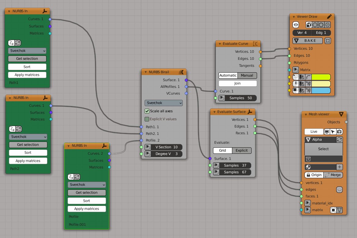
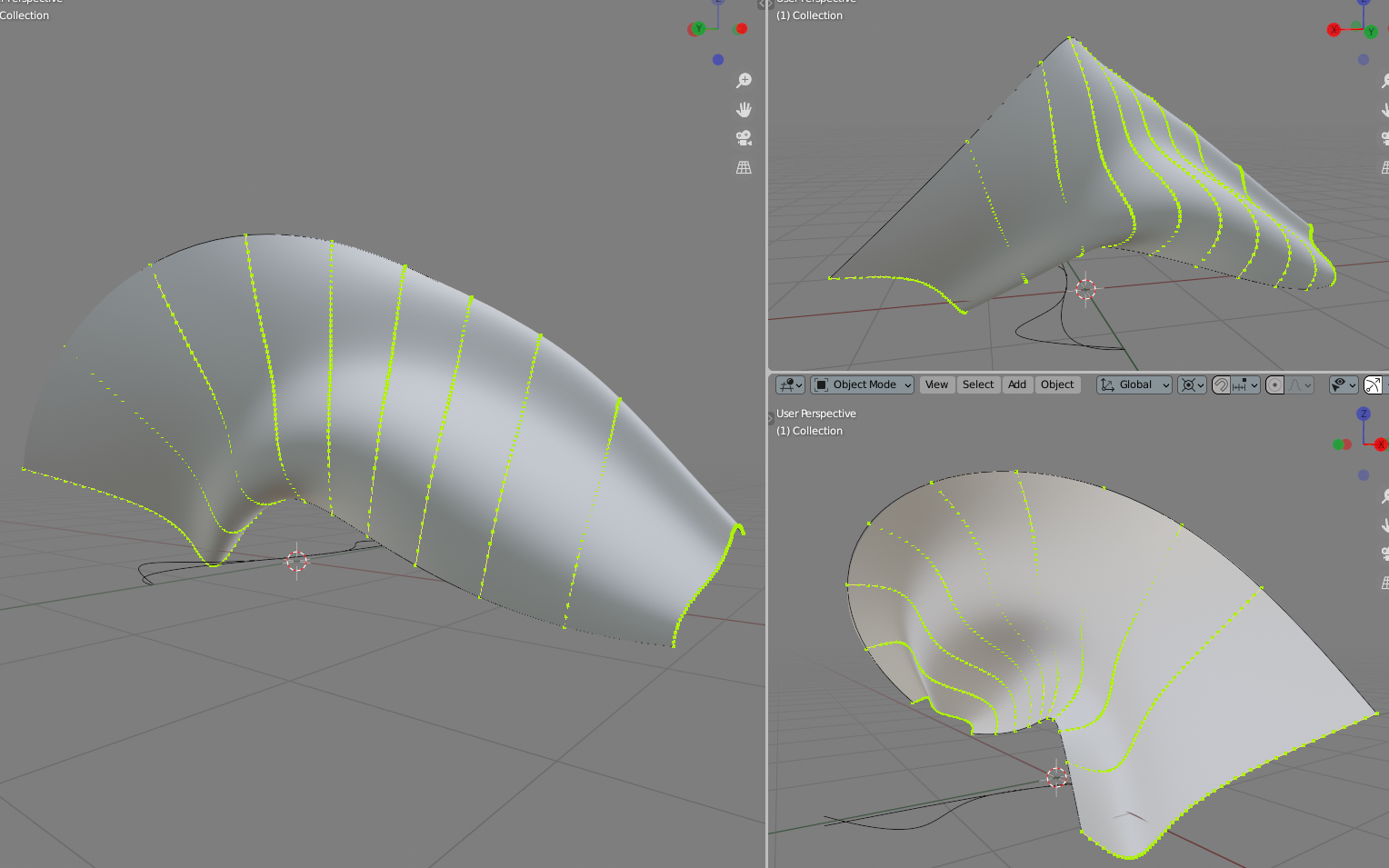
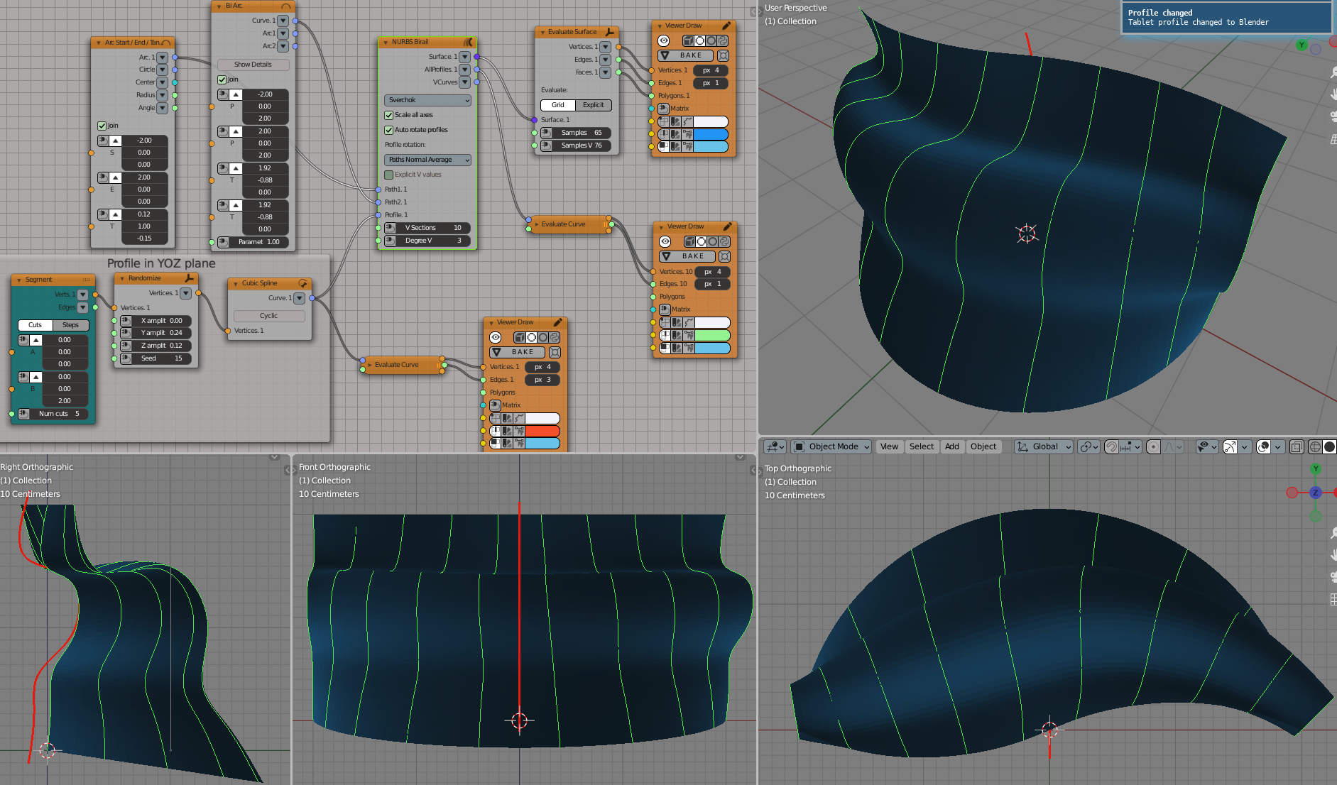
Create a circular arc (path 1) and S-shaped curve (path 2); use random profile curve in YOZ plane. Profile rotation = Path Normal Average (default one):
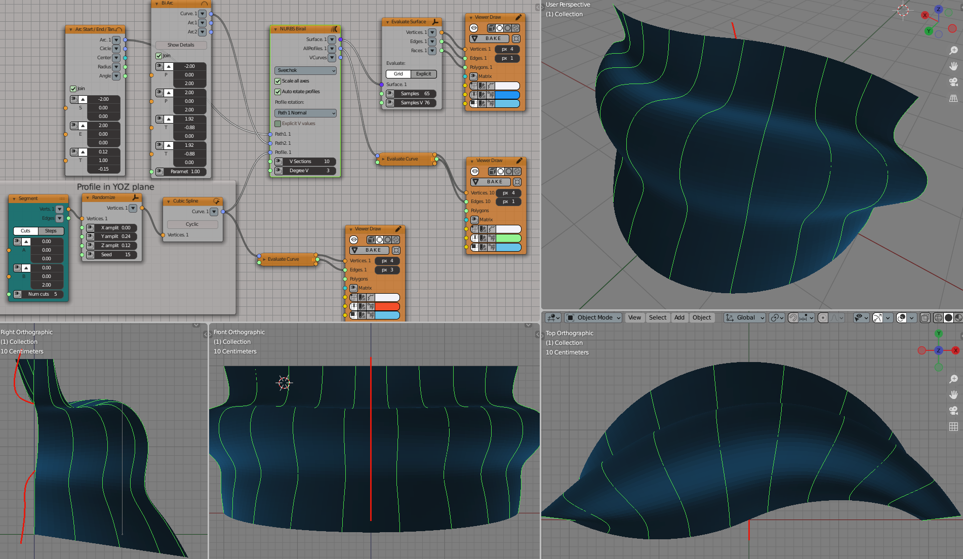
Same with Profile rotation = Path 1 Normal (i.e. profiles are perpendicular to the lower curve, circular arc):
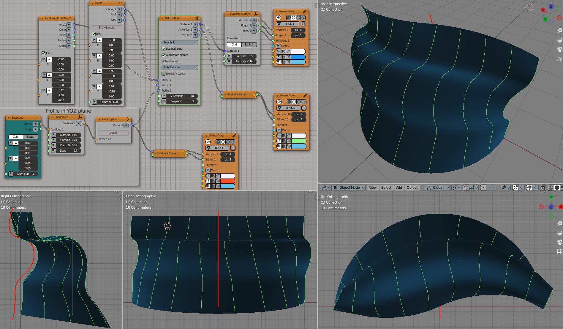
Same with Profile rotation = Path 2 Normal (i.e. profiles are perpendicular to the upper, S-shaped curve):
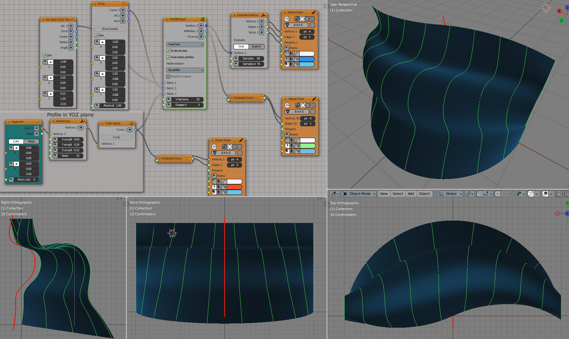
Same with Profile rotation = By profile, i.e. try to keep profile curves parallel to the original profile:
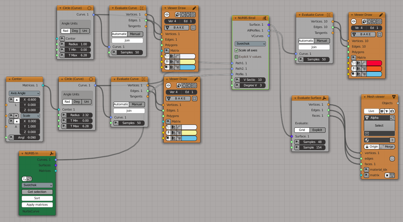
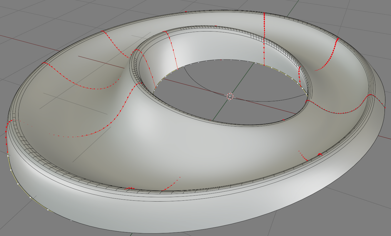
Another example; initial curves (with red points you can see how non-uniform is parametrization of path curves):
Loft algorithm result (with default “Path parameter uniform” distribution of profiles). Here we use low number of VSections (just 4 of them) to show that in such a case with Loft algorithm the surface may not follow path curves exactly:
Gordon algorithm result (with the same “path parameter uniform” distribution of profiles). The same numer of VSections is used. Now the surface follows paths exactly, but you can see that iso-curves of the resulting surface are going “diagonally” - that’s because path curves parametrization is non-uniform (and parametrization of two path curves is very different):
Gordon algorithm with “path length uniform” distribution of profiles. Here iso-curves go much more straight:
Tensor Product algorithm. Here iso-curves are “skewed” again, as for Lofting algorithm; but this time, the number of profile curve copies is calculated automatically (based on number of path curves control points), and the surface follows path curves exactly: