Adaptive Tessellate Surface#
Functionality#
This node generates an adaptive tessellation for the given surface, i.e. the mesh which represents the surface, and has smaller amount of subdivisions in places where the mesh is nearly flat and more subdivisions where the surface behaviour is more interesting.
In most cases, one converts a Surface object into a mesh by use of “Evaluate Surface” node. That node generates a subdivision by cartesian (rectangular) grid. However, in some cases a cartesian grid is not suitable. When the surface has some “almost flat” places and others, that are much more “bent” or even “sharp”, a naive cartesian grid approach:
generates too many points on flat areas
and generates too few points in the curvy areas.
This node generates points on the surface by following algorithm:
Start with a cartesian grid.
Then add more points into “most interesting” grid cells. “Interesting” cells may be defined as:
Having larger area (more precisely, area stretching factor)
Having bigger curvature value. Curvature may be defined as Gaussian curvature, mean curvature or as bigger one of the principal curvatures.
Number of vertices, which is to be added into each cell of the grid, is calculated proportionally to this “subdivision factor”.
Make a Delaunay triangulation of all these points.
And then map this triangluated thing onto the surface.
This approach can not automatically handle cases where the surface should have sharp edges. However, if we just happen to know where these sharp edges are, we can manually add points on these edges before building a Delaunay triangluation.
Also, this node can trim (cut) the surface by a trimming curve, similar to “Tessellate & Trim Surface” node. The provided trimming curve is supposed to be planar (flat), and be defined in the surface’s U/V coordinates frame.
Since the node uses Delaunay triangulation, it is enough to just apply “Dual Mesh” node after it to have a Voronoi subdivision.
Assumptions and Limitations:
This node uses a relatively simple algorithm without any “AI” or too complex computations involved. Thus, the node can not handle all cases. Especially,
The node can not generate very good subdivision if the surface has places where it is much more stretched along one direction compared to another. For example, if at some place a [0; 1] x [0; 1] square of U/V space is mapped onto a rectangular part of the surface with side lengths of 10 and 100 - the generated faces will appear stretched in one direction. However,
It will be okay if the rectangle will have sides of 100 and 130.
It will be okay if not only one part of the surface, but the whole surface is much more stretched in one direction than in another.
The node may not generate too good subdivision near the edges of the surface. Especially this is noticeable when the surface is supposed to be closed.
The node can not automatically detect where the surface is supposed to have “sharp edges” (if any). If you happen to know where such edges should be (in terms of surface’s U/V coordinates), use the “AddUVPoints” input.
When surface curvature values are used, the node may not handle very well so-called “singular points” of the surface (if it happens to have any) - places where different values of U/V coordinates are mapped into one point in space. For example, a sphere with usual polar parametrisation has such points at the poles.
Surface curvature values are calculated numerically, so they can be not very precise, especially with very “noisy” surfaces.
With high number of points to be generated, the node may be slow, especially when surface curvature values are considered.
Inputs#
This node has the following inputs:
Surface. The surface to be tessellated. This input is mandatory.
TrimCurve. The curve used to trim the surface. The curve is supposed to be flat and lying in the XOY plane. This input is optional.
SamplesU, SamplesV. Number of initial subdivisions in U and V directions (for the first step of the algorithm). The default value is 25.
SamplesT. The number of points to evaluate the trimming curve at. The default value is 100.
Min per cell. Minimal number of additional vertices, which is to be added into grid cells which have the least value of subdivision factor (area and/or curvature). The default value is 0 - do not add any vertices to such cells.
Max per cell. Maximum number of additional vertices, which is to be added into grid cells which have the greatest value of subdivision factor (area and/or curvature). The default value is 5.
Seed. Random seed value. The default value is 0.
AddUVPoints. Additional points in the surface’s UV space, which are to be added into subdivision before calculating Delaunay triangulation. For example, this may be useful to explicitly add vertices in places where the surface should have sharp edges. Only X and Y coordinates of provided vertices will be used. This input is optional.
Parameters#
This node has the following parameters:
By Curvature. Use surface curvature value to distribute additional points on the surface: places with greater curvatuer value will receive more points. The exact meaning of “curvature” is defined by Curvature parameter. Checked by default.
By Area. Use area stretching factor to distribute additional points on the surface. Area stretching factor is defined as area of rectangular grid cell mapped onto the surface divided by area of that cell in surface’s UV space. I.e., places where the surface is more stretched, will receive more vertices. Unchecked by default.
Curvature type. This parameter is available only when By Curvature parameter is enabled. This defines which exactly curvature value of the surface will be used. The available options are:
Maximum. Use the greater of absolute values of two principal curvature values. This option is the default one.
Gauss. Use the absolute value of Gaussian curvature.
Mean. Use the absolute value of mean curvature.
Please refer to Wikipedia for more information about these terms.
Trimming mode. This defines which part of the surface will be generated, when the trimming curve is used. The available options are Inner and Outer. The default value is Inner.
Curvature Clip. This parameter is available only in the N panel of the node, only when the By Curvature parameter is enabled. The calculated values of surface curvature will be restricted to do not exceed this number. This is used to ignore places on the surface where it has too high values of curvature (sharp points) - otherwise the algorithm would be placing all the additional points to such places. The default value is 100. Usually you do not have to change this value. Set the parameter to 0 (zero) to disable this part of the algorithm.
Trim Accuracy. This parameter is available in the node’s N panel only. This defines the precision of the trimming operation. The default value is 5. Usually you do not have to change this value.
Outputs#
This node has the following outputs:
Vertices. Generated vertices on the surface.
Faces. Generated faces (they are all triangles).
UVPoints. Points represenging U/V coordinates of all generated vertices on the surface. Z coordinates of these points is always zero.
Examples of Usage#
Motivating example. Let’s consider a surface which is made out of plane with several bumps. On the left: a surface evaluated with cartesian grid; on the right: the same surface with adaptive tessellation. Each of these meshes has (nearly) the same count of triangles - 41K.
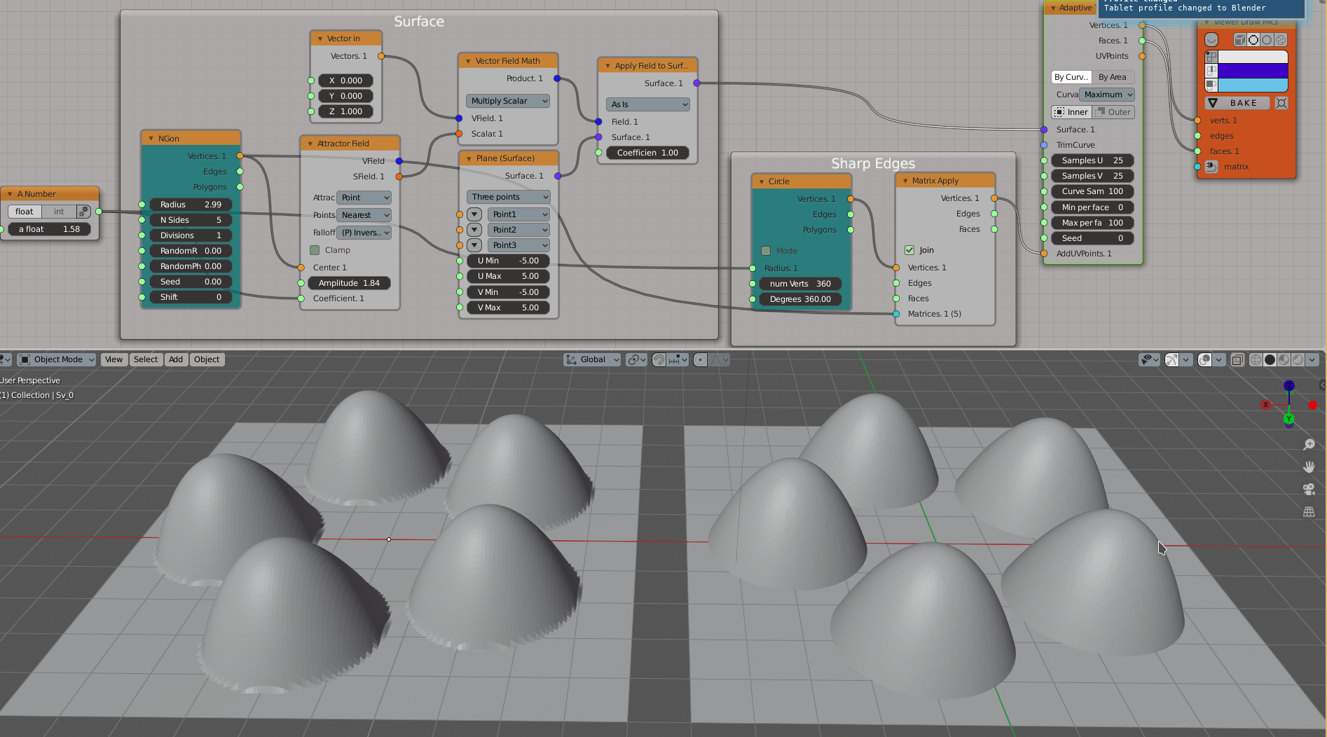
Notice how much smoother the bumps are on the right mesh. Also notice the sharp edges around the bumps - they are made by explicitly defining the points where they should be (by use of AddUVPoints input).
The same pictue with wireframe display enabled:
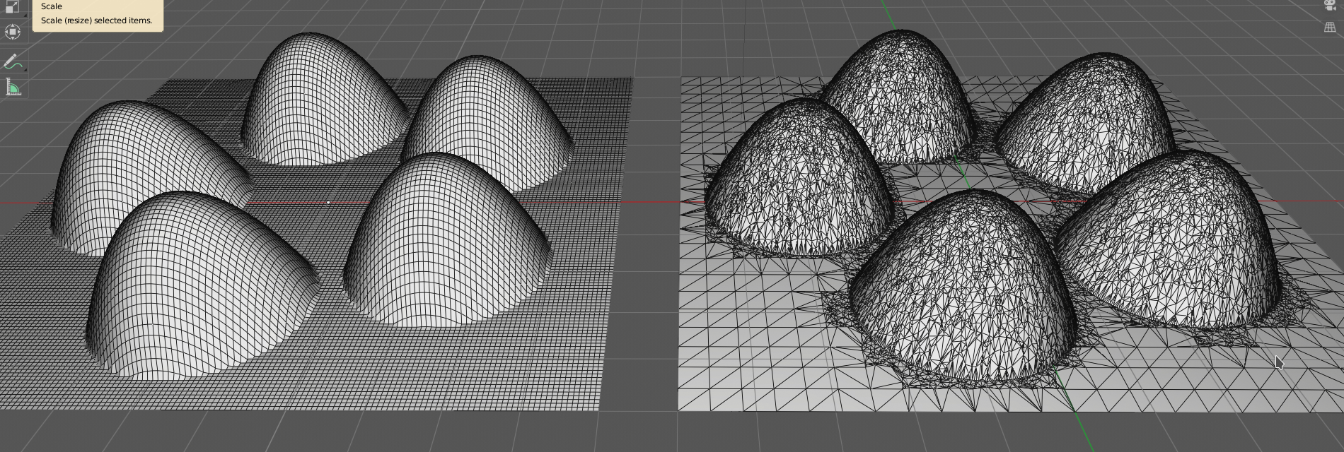
Notice that on the left, the mesh has a lot of subdivisions in the flat part, where they are not at all necessary. The right mesh has much less subdivisions in flat parts, and much more on the bumps.
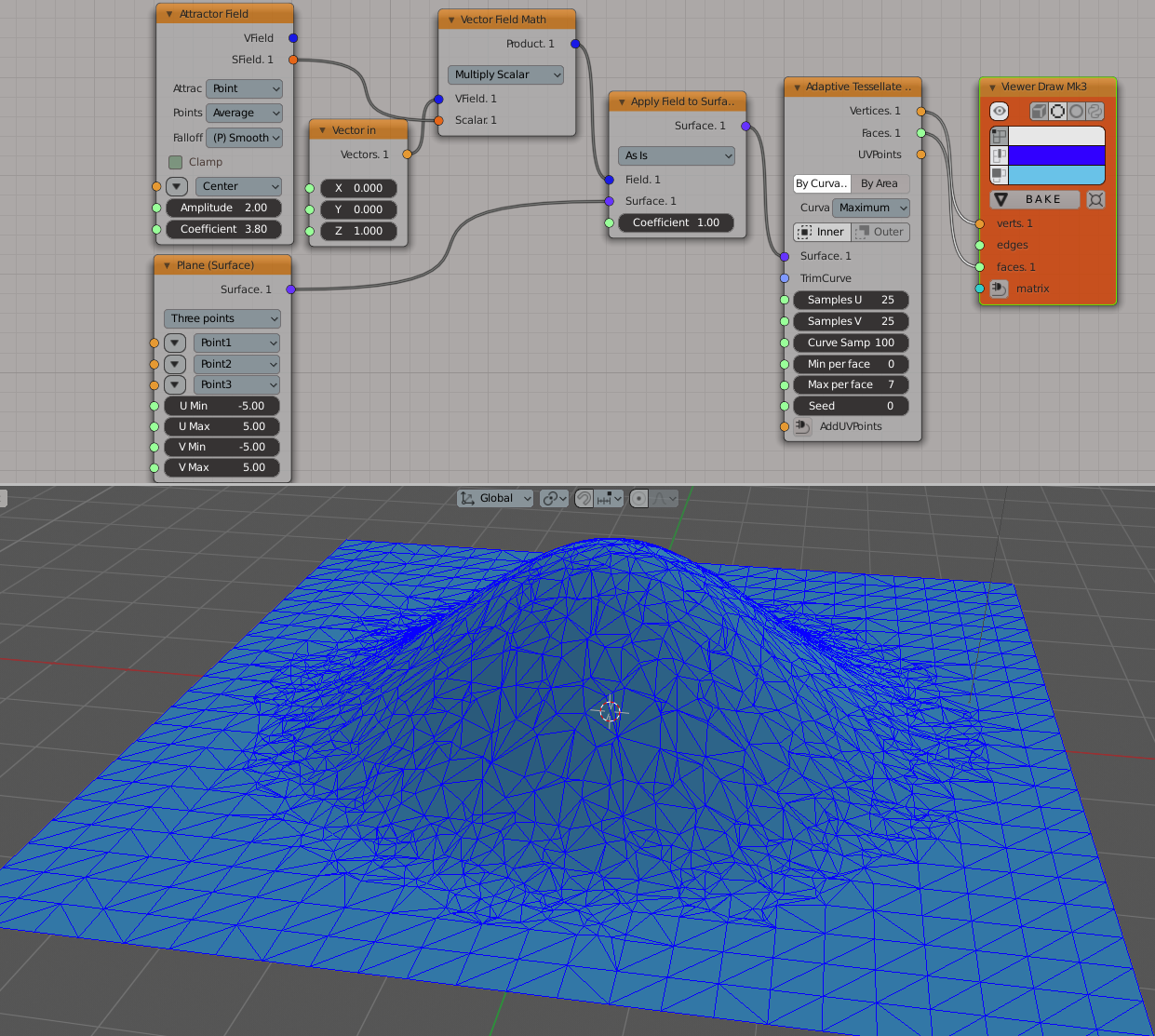
A simpler example, with one bump and no additional points used:
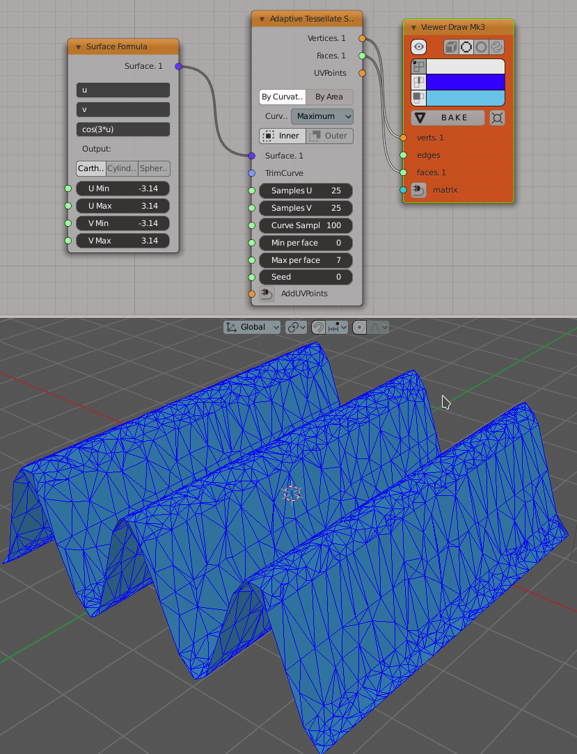
Use of the node with formula-defined surface, with only By Curvature parameter enabled. Notice that there are more subdivisions in the places where the surface is bent:
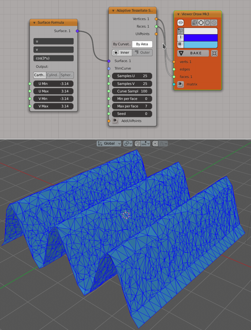
The same surface with only By Area parameter enabled. Here there are more subdivisions in places where the surface is stretched (but it is almost flat at these places):
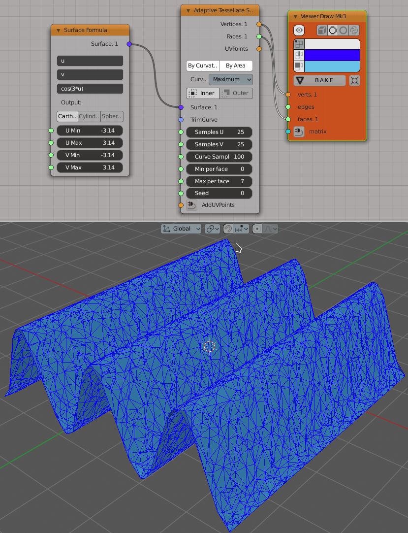
And with both parameters enabled at the same time:
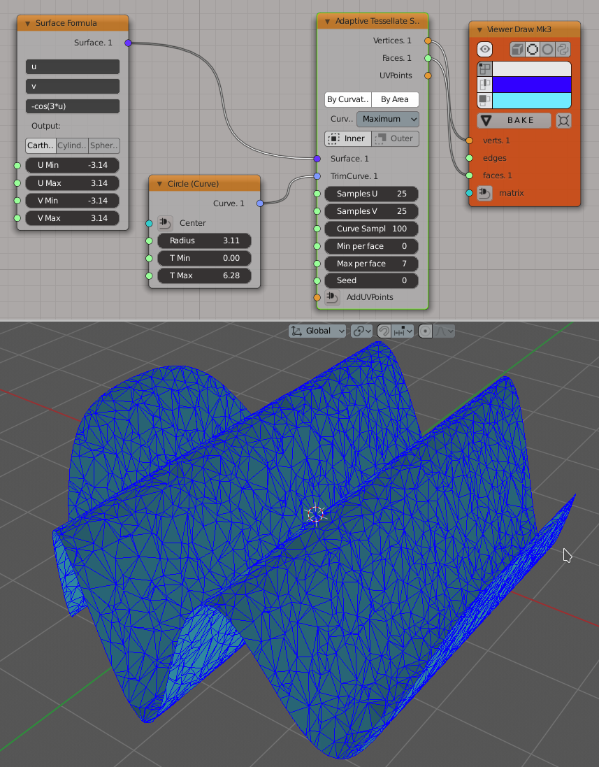
An example of the TrimCurve input usage: