Viewer Draw Surface#
Functionality#
This node displays Surface objects in the 3D View, using opengl. The node is intended to be a fast way to show you the result of your node tree.
For NURBS and NURBS-like surfaces, the node can also additionally display control points and control net edges. For non-NURBS curves, the node just does not try to display these attributes.
This node is automatically created when you select “Connect Viewer Draw” from right-click menu for nodes which have Surface output. Also this node pops up as a “temporal viewer”. when you perform control-click on such a node.
Inputs#
This node has the following inputs:
Surface. The surface object(s) to be displayed. This input is mandatory.
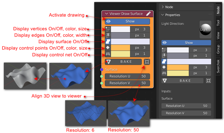
Resolution U, Resolution V. Resolution to display the surface, along U and V parameters. The default value is 50.
Parameters#
This node has one main parameter:
Show. The node displays something only when this parameter is enabled.
Most parameters of this node are grouped in rows; for each type of information this node can display, there are three parameters: whether to display it, the color to be used, and point size / line width to be used.
The parameters of the node are (in this order):
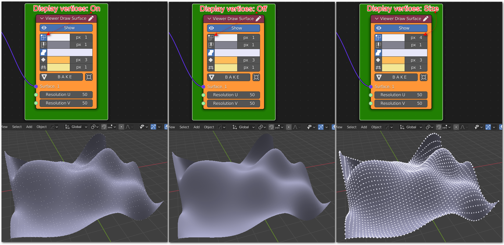
Display Vertices, Vertices Color, Vertices Size. Control display of points on the surface (number of points along U and V parameters are controlled by Resolution U, Resolution V inputs). Display of points is disabled by default.
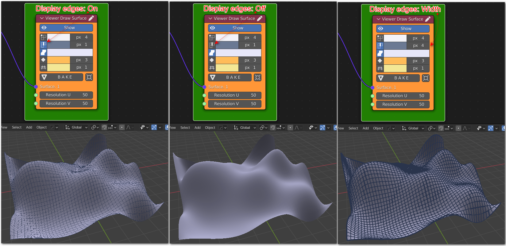
Display Edges, Edges Color, Edges Line Width. Control display of edges on the curve (edges between points). Display of edges is disabled by default.
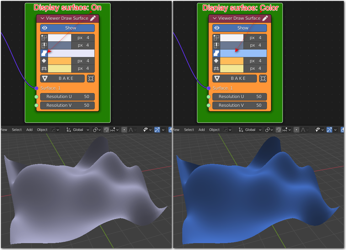
Display Surface, Surface Color. Control display of the surface itself. The surface is shown by default.
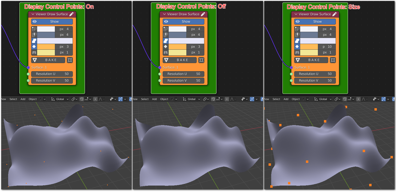
Display Control Points, Control Points Color, Control Points Size. Control display of surface’s control points, for NURBS and NURBS-like surfaces. Control points are not shown by default.
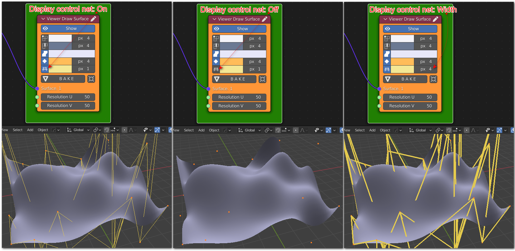
Display Control Net, Control Net Color, Control Net Line Width. Control display of surface’s control net (edges between control points), for NURBS and NURBS-like surfaces. Control net is not displayed by default.
Display Node Lines, Node Lines Color, Node Lines Width. Conrtol display of node lines, i.e. isolines at U and V parameters according to node values of knotvectors along U and V parameter directions. Node lines are not displayed by default.
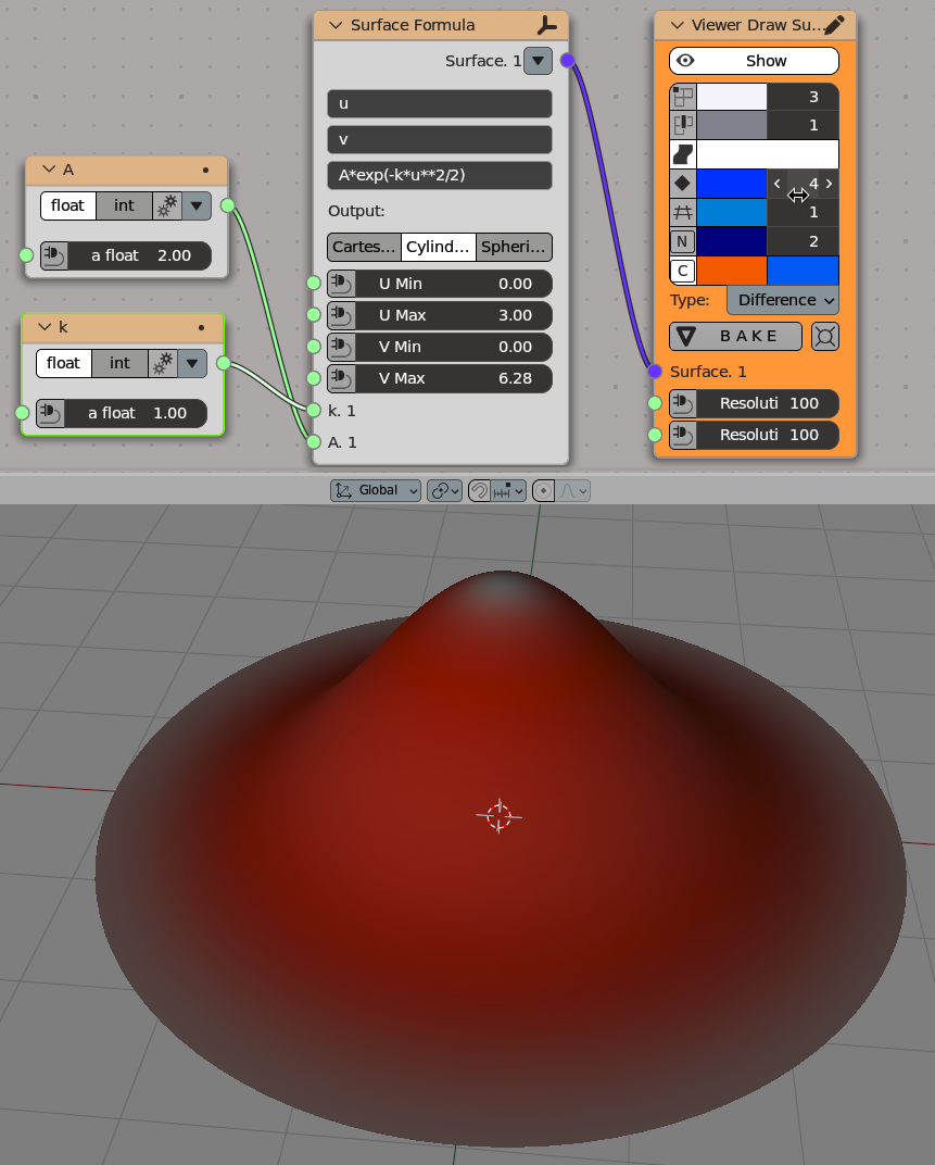
Indicate Curvature, Minimum Curvature Color, Maximum Curvature Color. Control indication of surface curvature. Colors control how places with minimum and maximum curvature value will be indicated on surface. Places with medium curvature values will be drawn with Surface Color, as usual. The Type dropdown is visible only when Indicate Curvature is checked, and it controls what type of curvature should be indicated:
Gauss - indicate Gauss curvature (product of minimum and maximum curvature). Places with positive Gaussian curvature are where the surface behaves like sphere. Places with negative Gaussian curvature are where the surface is like a saddle.
Mean - indicate mean curvature (sum of minimum and maximum curvature).
Maximum - indicate maximum curvature, i.e. the biggest of two principal curvature values.
Minimum - indicate minimum curvature, i.e. the smallest of two principal curvature values.
Difference - indicate difference between maximum and minimum curvature values. Places where difference is zero, i.e. maximum curvature equals minimum curvature, are umbillic points.
Operators#
This node has the following buttons:
BAKE. Create mesh objects in Blender scene according to curves being displayed.
Align. Zoom and position 3D view so that generated object is in the center.
Outputs#
This node has no outputs.
Example of Usage#
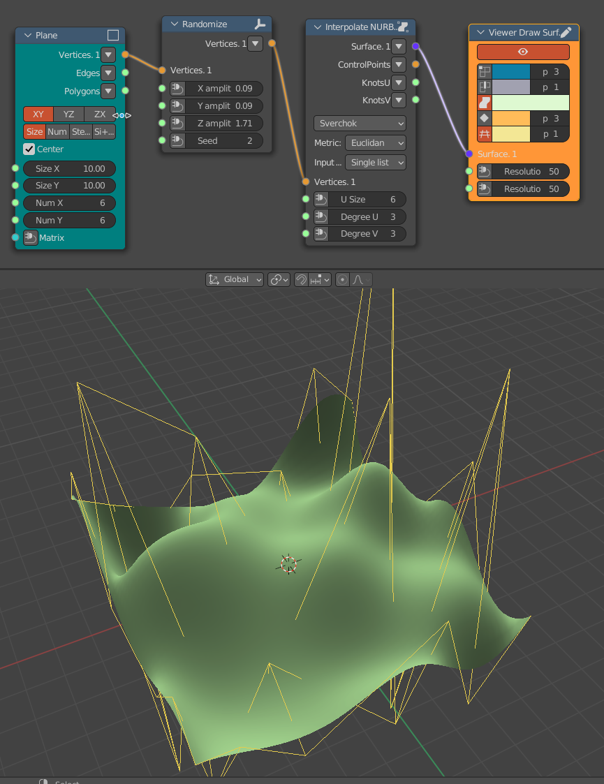
Generator-> Plane
Transform-> Randomize
Surfaces->NURBS-> Interpolate Nurbs Surface
Examples of surface curvature indication:
Gaussian curvature:
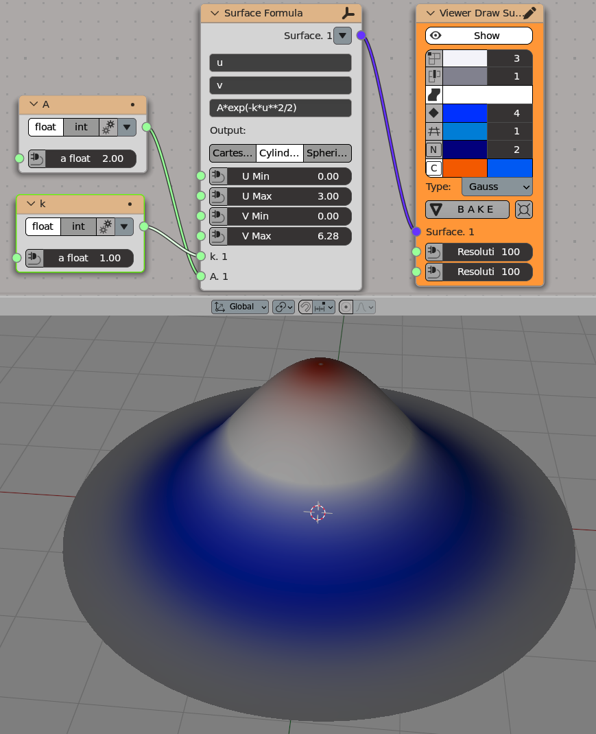
Another surface with indicated Gaussian curvature:
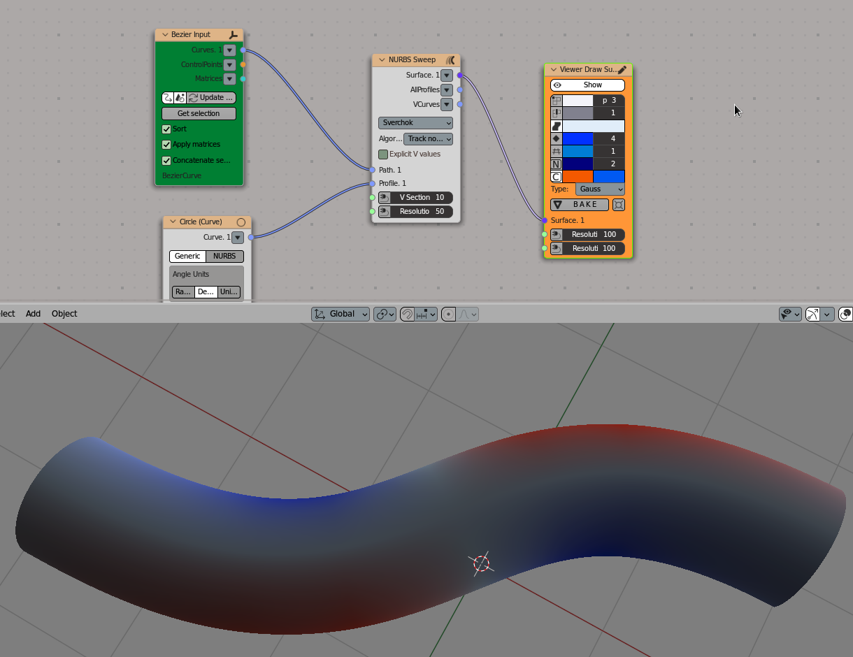
Mean curvature:
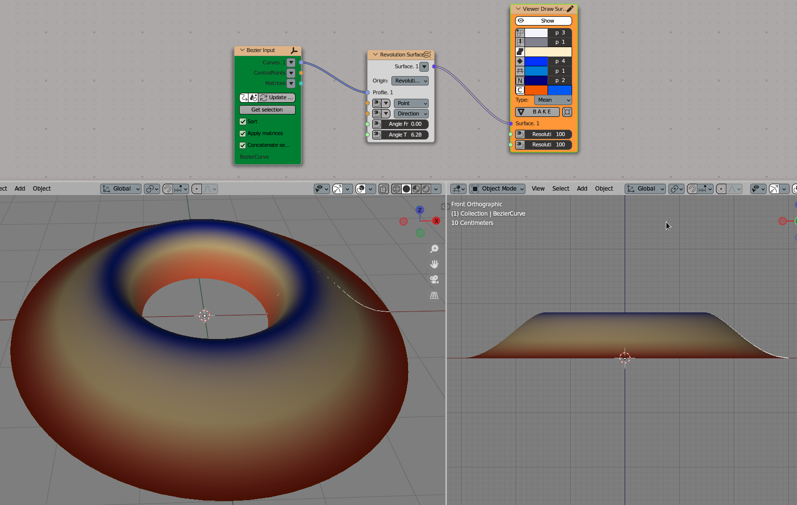
Difference of two curvatures:
