Conic Sections#


Functionality#
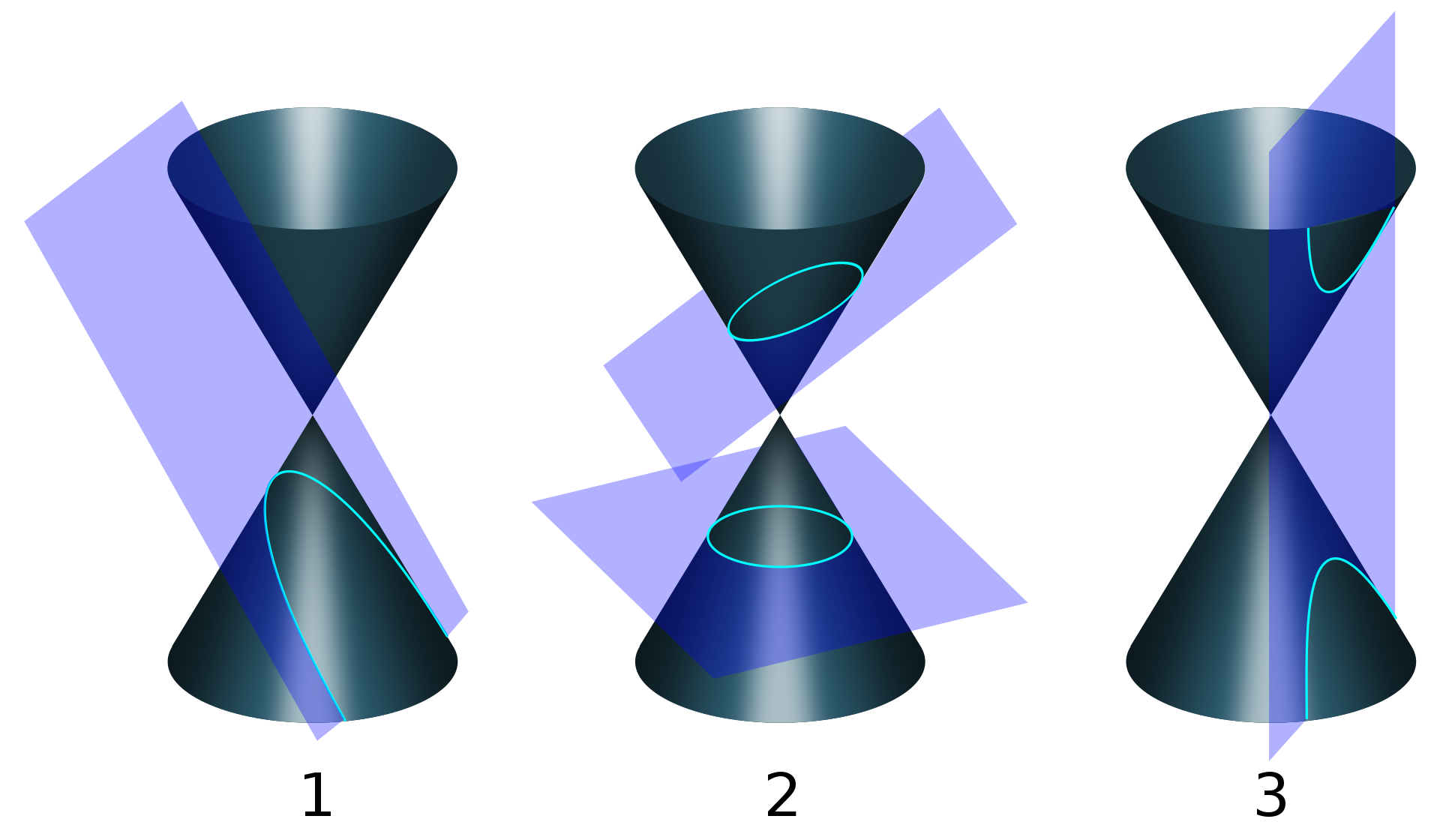
This node generates conic sections by definition: by generating an (endless) cone, (endless) plane and calculating their intersection. As we know, the intersection may be an ellipse, a parabola or a hyperbola:

A cone may be defined by either
A point (which is called apex or vertex), axis direction vector and an angle between generatrix and axis;
Or an apex, axis direction vector and a generatrix direction vector.
A plane is defined by a point and a normal vector.
Inputs#
This node has the following inputs:
ConeApex. An apex point of the cone. The default value is (0, 0, 0).
ConeDirection. Cone axis direction vector. The default value is (0, 0, 1).
Count. Count of generatrices to generate. This defines the maximum number of vertices this node can generate. Actual number of vertices may be fewer, because some generatrices may not intersect the specified plane. The default value is 16.
Generatrix. Cone generatrix direction vector. This input is available only if cone definition mode parameter is set to Generatrix. The default value is (0, 1, 1).
ConeAngle. An angle between cone axis and it’s generatrix. This input is available only if cone definition mode parameter is set to Angle. The default value is pi/6.
Max Distance. Maximum distance between cone apex and generated vertices. Vertices that are farther from apex will not be generated. The default value is 100.
PlanePoint. A point lying on a plane (used to define the plane). The default value is (0, 0, 1).
PlaneDirection. A normal vector of a plane (used to define the plane). The default value is (0, 0, 1).
Parameters#
This node has the following parameters:
Define Cone. Specifies the way of defining the cone. Available values are Angle and Generatrix. The default value is Angle.
Even Distribution. If checked, then generated vertices will be evenly distributed across the generated curve. Otherwise, positions of generated vertices will be defined by intersections of the cone generatrices and the specified plane. Unchecked by default.
Interpolation Mode. Defines the way of interpolating vertices location in case when Even Distribution parameter is checked. Available values are Linear and Cubic. The default value is Linear.
Outputs#
The node has the following outputs:
Vertices. The vertices of the output curve.
Edges. The edges of the output curve.
BranchMask. Mask values defining to which curve branch does the curve vertex belong. This is useful for hyperbolas only. For other curves, this output will contain all 0s or all 1s.
SideMask. Mask values defining to which side of the curve does the vertex belong (“right” or “left”). For cases when sides of the curve can not be distinguished (for circles, for example), this output will contain all 1s.
Examples of Usage#
Classic parabola is defined by a cone and a plane which is parallel to cone’s generatrix:

Viz-> Viewer Draw
The same parabola but with “even distribution” turned on:

Viz-> Viewer Draw
Classic ellipse is defined by a cone and a plane which intersects the cone at some random angle:

Curves-> Curve Segment
Vector-> Vector In
Viz-> Viewer Draw
One can generate a series of curves by intersecting one cone with a series of planes at different angles:

Number-> Number Range
Vector-> Vector In
Vector-> Vector Polar Input
Vector-> Vector Rewire
Modifiers->Modifier Make-> UV Connection
Viz-> Viewer Draw
One can generate a hyperbola (2-branched curve) and then use it to generate 1-sheet hyperboloid

Modifiers->Modifier Change-> Mask Vertices
CAD-> Lathe
Viz-> Viewer Draw
or 2-sheet hyperboloid

Modifiers->Modifier Change-> Mask Vertices
CAD-> Lathe
Viz-> Viewer Draw
There are more examples in the original thread.