Solid from two Faces#
Dependencies#
This node requires FreeCAD library to work.
Functionality#
This node generates a Solid object from two Faces (“floor” and “ceiling”) by adding linear surfaces to connect their edges (“walls”).
NOTE: the node requires that two Face objects provided have exactly the same number of edges. Hint: if you are generating Faces from Curves, you can use “Split Curve” node to increase the number of edges.
Depending on the way how you generate “floor” and “ceiling” surfaces, it can appear that the order or the direction of their edges will be incorrect; in such cases weird invalid bodies would be generated. To deal with such cases, the node suggest options to reverse the order of edges, or direction of edges.
By default, the node will check that the Solid object it constructed is “valid” in terms of FreeCAD’s OCCT kernel: all faces have coinciding edges, all normals are pointing outside, and so on. If the node will find that the solid is not valid, it will try to automatically fix it. If this automatic fix process fails, the node will raise an exception (become red) and processing will stop.
NOTE: some operations with Solid objects which are not “valid” are known to cause crashes. So it is strongly recommended to have “Validate” parameter turned on.
Solid Face object can be created with nodes from “Make Face” submenu (such as “Face from Curve”); also any NURBS or NURBS-like surface can be used as a Solid Face.
Inputs#
This node has the following inputs:
SolidFace1. The first Solid Face object (to be used as “floor”, for example). This input is mandatory.
SolidFace2. The second Solid Face object (to be used as “ceiling”, for example). This input is mandatory.
Parameters#
This node has the following parameters:
Flip Face 1, Flip Face 2. If checked, the node will flip first or second Face, correspondingly (invert it’s normal direction). It can be required to build a proper Solid object. Unchecked by default.
Rev. Edges 1, Rev. Edges 2. If checked, the node will reverse the order of edges of first or second Face, correspondingly. It can be required to build a proper Solid object. Unchecked by default.
Flip Edges 1, Flip Edges 2. If checked, the node will reverse the direction of each edge of first or second Face, correspondingly. It can be required to build a proper Solid object. Unchecked by default.
Validate. This parameter is available in the N panel only. If checked, the node will check that the Solid object it constructed is “valid” in terms of FreeCAD’s OCCT kernel: all faces have coinciding edges, all normals are pointing outside, and so on. If the node will find that the solid is not valid, it will try to automatically fix it. If this automatic fix process fails, the node will raise an exception (become red) and processing will stop. So if this parameter is checked, you can be sure that the generated Solid object is “valid”. If not checked, the node will not validate the created object. In most cases, you have to check this parameter; it is checked by default. NOTE: some operations with Solid objects which are not “valid” are known to cause crashes.
Tolerance. This parameter is available in the N panel, only if Validate parameter is checked. Tolerance for automatic “fix” process. The default value is 0.001.
Outputs#
This node has the following output:
Solid. The generated Solid object.
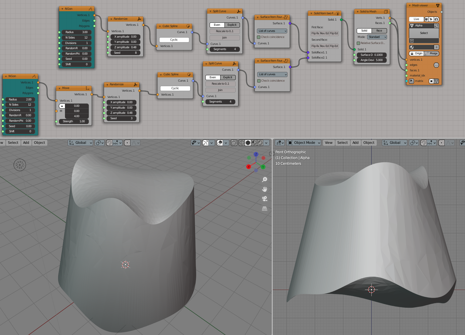
Example of usage#
Generate two cubic splines from randomized polygons; subdivide each spline into four parts, to build a Coons surface from each of them; then connect these two surfaces into one Solid: