Solid General Fuse#
Dependencies#
This node requires FreeCAD library to work.
Functionality#
This node finds Boolean intersections of several Solid object at once, and allows one to combine resulting parts in different ways. This is a generalized, more complex, but more powerful, analog of “Solid Boolean” node: all what “Solid General Fuse” node does can be done with several consequential applications of “Solid Boolean” node. For complex boolean operations on many parts, one application of “Solid General Fuse” will give you better performance compared to many “Solid Boolean” applications.
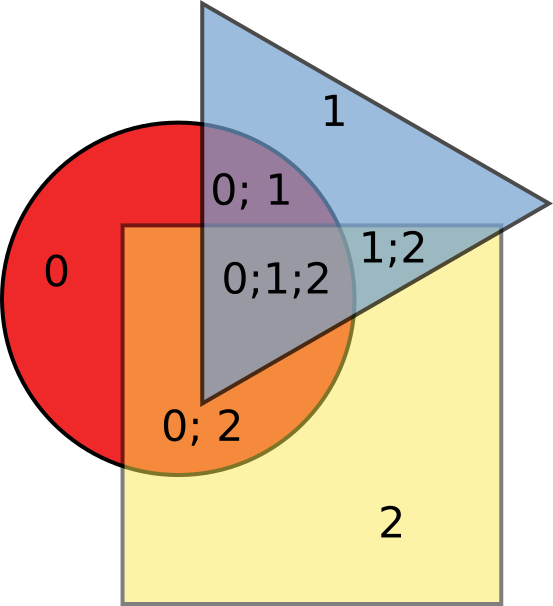
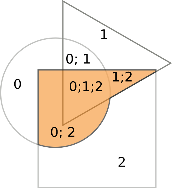
To illustrate what exactly this node does, it’s simpler to draw some 2D pictures first. Let’s say we have a circle (object number 0), a triangle (object number 1) and a square (object number 2):
(Figure 1)
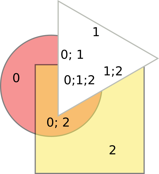
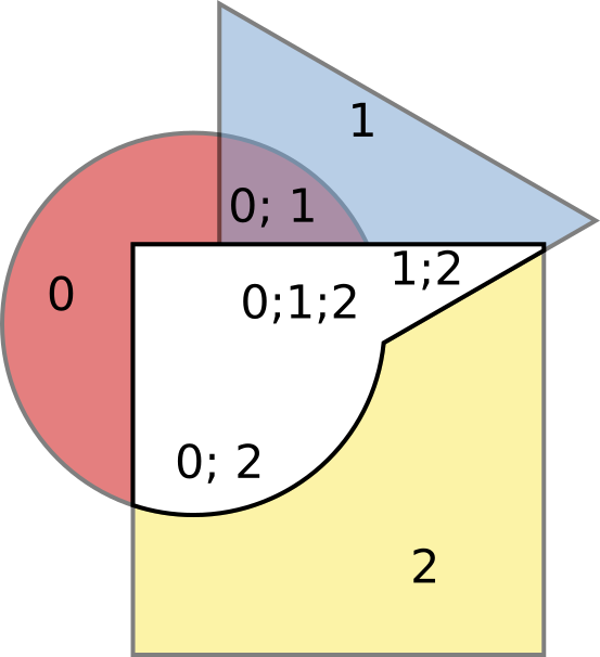
If they are overlapping somehow, they constitute several areas (7 in this case), and each area comes from some of source objects. On the illustration above, it is indicated which areas come from which object. We will say that each part of such figure has some “set of source objects”. For example, the part in the middle, which is the intersection of all three objects, has set of source objects equal to [0, 1, 2]. Now, we can take some of these 7 areas and combine them, and throw the others part out. To do this, we have to identify, which parts we like, and which we do not. For example, let’s exclude all parts that come from the triangle, i.e. for which the set of source objects includes object number 1:
(Figure 2)
(the triangle is now white to illustrate where it was; colored part is what is left). Or, we can exclude parts, for which the set of source object includes 0 and 1, i.e. we remove the intersection of the circle and the triangle:
(Figure 3)
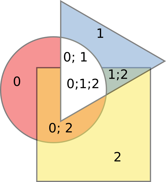
Or, let’s leave only parts, for which the set of source objects is [0,2],
[0,1,2], and [1,2]:
(Figure 4)
Or, let’s remove those parts and leave all others:
(Figure 5)
In 3D, things are more complex, but general idea is the same.
To identify, which parts to leave and which to remove, this node has two inputs, Include and Exclude. In the end, you will have only parts that are Included, and at the same time not Excluded. Parts are identified by lists of integers - indexes of source Solid objects each part came from (sets of source objects). The node supports two modes of how sets of source objects can be specified:
By exact match. If you specify set of source objects like
[0, 1], then only parts which came from source solids number 0 and number 1 (at the same time, i.e. from intersection of these objects) will be identified. For example, a part with set of source objects[0, 1, 2]will not be identified.By subset. If you specify set of source objects like
[0, 1], then all parts, for which the set of source objects includes 0 and 1, will be identified. For example, parts with sets of source objects[0, 1],[0, 1, 2],[0, 1, 3]will be identified.
For each of inputs (Include and Exclude), the node can process a list of sets
of source objects; they are joined by OR. For example, if for Include input you
have “Exact” mode, and you’ve provided [[0, 1], [2,3]], then you will have
parts that come from intersection of bodies number 0 and 1, OR from
intersection of bodies number 2 and 3.
If neither Include or Exclude input is connected, then the node will output all parts of all intersections.
After such playing, we can either fuse the remaining parts into one object, or leave them as different objects.
This node can also produce information about which element of the resulting Solid object came from which source object.
Inputs#
This node has the following inputs:
Solids. The Solid objects to operate on. This input can consume list of Solids or list of lists of Solids. This input is mandatory.
Include. List of sets of source objects, which identify which parts are to be included in the resulting body (see Functionality section above). If not connected, this means “Include all what is not excluded”.
Exclude. List of sets of source objects, which identify which parts are to be excluded from the resulting body (see Functionality section above). If not connected, this means “do not exclude anything”.
Parameters#
This node has the following parameters:
Merge Result. If checked, the node will fuse all parts that are selected by Include and Exclude inputs, into one Solid object. Otherwise, the node will output each part as a separate Solid object. Checked by default.
Refine Solid. This parameter is available only when Merge Solid parameter is checked. If checked, the node will refine the generated object, by removing unnecessary edges. The result will be more clean; but in this case the node will not be able to correctly calculate data for EdgesMask, EdgeSources, FacesMask, FaceSources outputs, so these outputs will be hidden. Checked by default.
Include mode (located near Include input). This defines how the parts to be taken are identified. The available options are Exact and Subset. The default option is Exact. See Functionality section above for description.
Exclude mode (located near Exclude input). This defines how the parts to be removed are identified. The available options are Exact and Subset. The default option is Exact. See Functionality section above for description.
Outputs#
This node has the following outputs:
Solid. The generated Solid objects. If Merge Result parameter is checked, this node will contain one Solid object for each list of Solid objects in the Solids input. Otherwise, it will contain a list of Solid objects for each list of Solid objects in the Solids input.
SolidSources. For each Solid object in the Solid output, this output contains a list of indexes of source Solid object, from where these resulting Solid parts came from.
EdgesMask. Mask for Edges of generated Solid object, which is True for edges that come from more than one source object. For Intersect operation, this mask will always contain all True. This output is only available when Merge Result parameter is not checked, or when Refine Solid parameter is not checked.
EdgeSources. For each Edge of generated Solid object, this output contains a list of indexes of source objects, from which this edge came. See more detailed explanation below. This output is only available when Merge Result parameter is not checked, or when Refine Solid parameter is not checked.
FacesMask. Mask for Faces of generated Solid object, which is True for faces that come from more than one source object. For Union operation, this output contains all False, because all “common” faces are always inside the body. This output is only available when Merge Result parameter is not checked, or when Refine Solid parameter is not checked.
FaceSources. For each Face of generated Solid object, this output contains a list of indexes of source objects, from which this face came. This output is only available when Merge Result parameter is not checked, or when Refine Solid parameter is not checked.
The following illustrates how EdgeSources output is calculated (here Solid Boolean node is used, but General Fuse node works the same way):
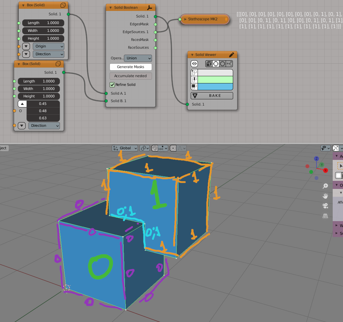
Here we have two cubes, 0 and 1. Purple edges came from cube 0, for them
EdgeSources output contains [0]. Orange edges came from cube 1, for them
EdgeSources output contains [1]. Edges marked with cyan came from both
cubes, for them EdgeSources output contains [0, 1].
FaceSources output is calculated similarly, but for faces instead of edges.
Examples of Usage#
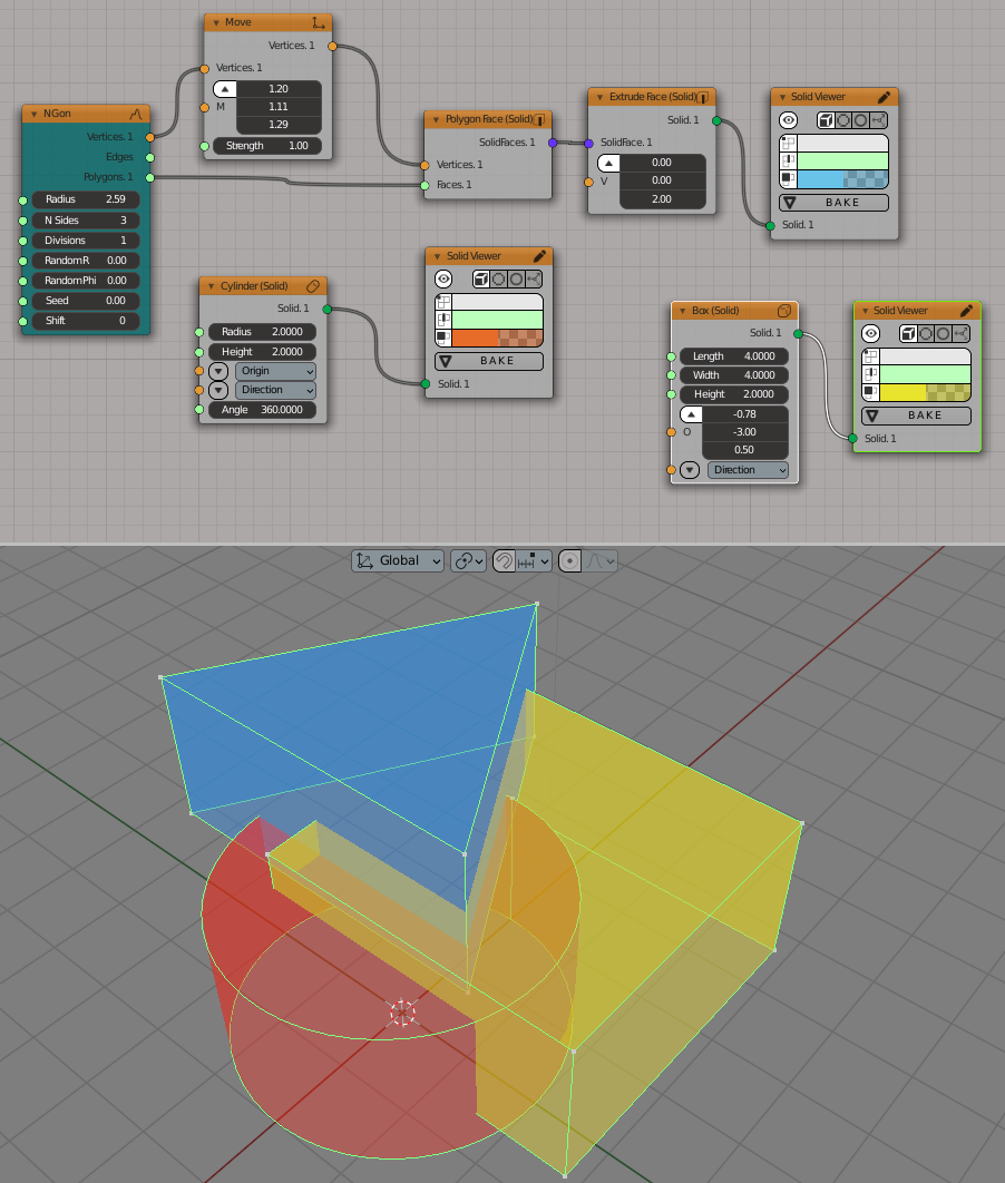
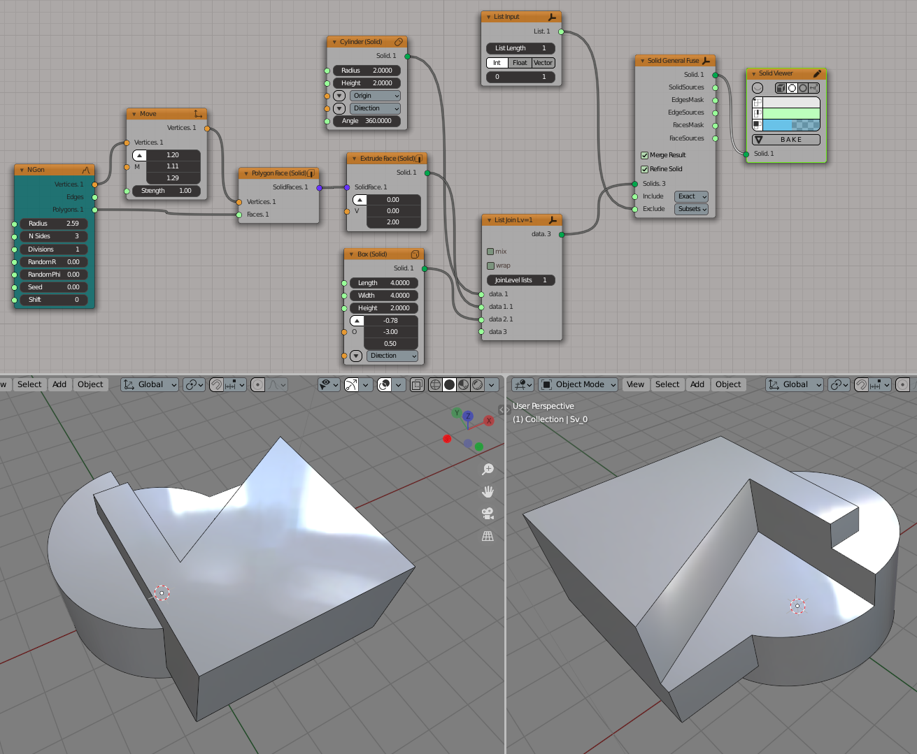
First, let’s reproduce Figure 1 in 3D:
Now we reproduce Figure 2 in 3D:
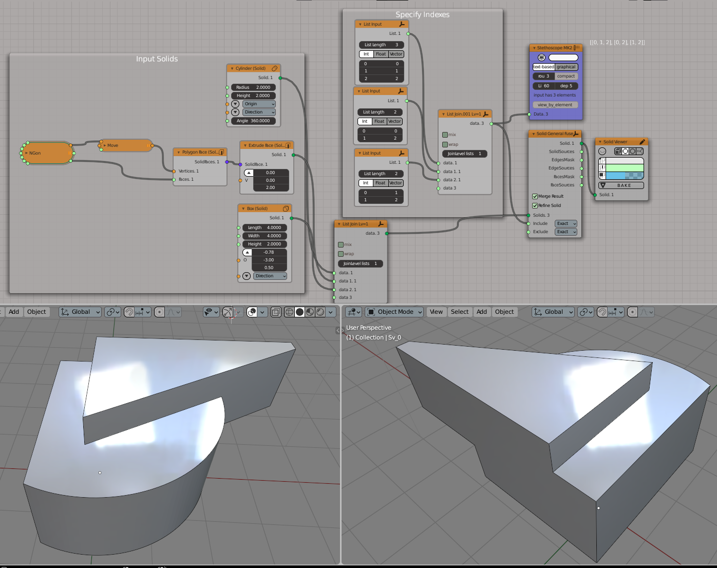
Reproduction of Figure 4:
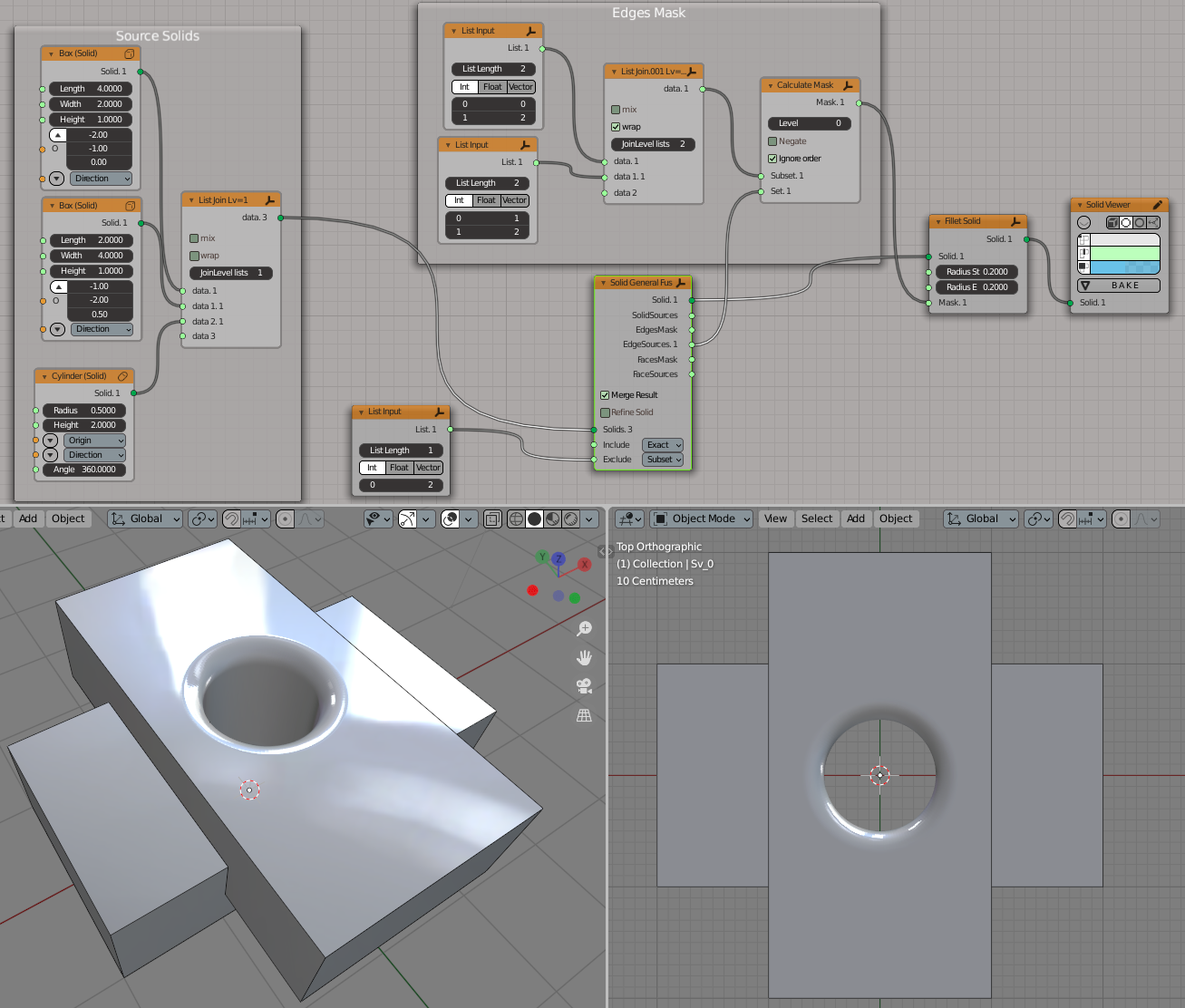
An example of EdgeSources output usage: make a fillet on edges which come from intersection of objects #0 and #2, or objects #1 and #2: