
Adaptive Polygons Mk2#
Functionality#
This node puts a (transformed) copy of one object, called donor, along each face of another object, called recipient. Copies of donor objects are deformed (adapted) to match the shape and normals of recipient’s face.
This node works primarily with Quads and Tris; if you ask it to work with NGons (N > 4), it can produce weird results.
As an option, the node can process NGons (and Quads / Tris, optionally) in so called “Frame / Fan” mode. In this mode, each face of recipient mesh is inset by some amount, so it is replaced with a number of either Quads or Tris. Each of such faces is then processed as usual.
Or one can pass recipient object through Inset Special node to achieve results similar to Tissue’s “Fan” or “Frame” modes.
In many cases it is good idea to pass the output of this node through Remove Doubles node.
This node is based on original code taken with permission from https://sketchesofcode.wordpress.com/2013/11/11/ by Alessandro Zomparelli (sketchesofcode). Further features were developed after the Tissue addon by Alessandro.
Inputs#
This node has the following inputs:
Vertices Recipient. Vertices of the recipient object. This input is mandatory.
Polygons Recipient. Faces of the recipient object. Please have in mind that order of indices in each face affect donor object rotation; for example, [0, 1, 2, 3] is one rotation, [3, 0, 1, 2] is the same turned by 90 degrees. This input is mandatory.
Vertices Donor. Vertices of the donor object. This input is mandatory.
Edges Donor. Vertices of the donor object. This input is mandatory.
Pols Donor. Faces of the donor object.
FaceData Donor. List containing an arbitrary data item for each face of donor object. For example, this may be used to provide material indexes of donor object faces. Optional input.
Width coeff. Coefficient for donor object width (size along X,Y axis, usually). Default value is 1.0. The input expects one number per each recipient object face.
Frame width. Width of frame for “Frame / Fan” mode. Maximum value of 1.0 means that there will be no gap in the center of face, so this will be “Fan” mode. Default value is 0.5. This input is available only if Frame mode parameter is set to value other than Do not use.
Z coeff. Coefficient for donor object size along recipient object face normal. Exact meaning depends on Z Scale parameter (see below). The default value is 1.0. The input expects one number per each recipient object face.
Z offset. Offset of donor objects along the normal of recipient object face. Default value is 0.0. The input expects one number per each recipient object face.
Z Rotation. Rotation of donor objects along the normal of recipient object face, in radians. Default value is 0.0. The input expects one number per each recipient object face.
Polygon Rotation. Rotation of each recipient object face indexes. The default value is 0. For example, if recipient face definition is [3, 4, 5, 6], and Polygon Rotation is set to 1, then the face will be interpreted as [4, 5, 6, 3]. This will affect the orientation of donor object.
Polygon Mask. Mask for recipient object faces processing. What exactly will be done with faces which are masked out is defined by Mask Mode parameter (see below).
Threshold. Merging threshold for “remove doubles” / “merge by distance” function. The default value is 0.0001. This input is only visible if Remove doubles parameter is checked.
Donor Index. Determine which donor to use for each face. This input is only visible if Matching Mode is set to Donor per face and Donor Matching is set to By Index (see below).
Use normals. This defines how recipient object normals will be used to transform the donor objects. Available values are:
Map. Interpolation between recipient object’s vertex normals will be used to deform the donor object. While this produces smoother results, this gives more deformation of donor object.
Face. Recipient object’s face normal will be used to orient the donor object. While this gives less deformation of donor object, it can give gaps between copies.
The default value is Map.
Custom Normal. This vector input will replace the normals of the recipient meshes. It will only work if Custom Normals is set to Normal per Vertex or Normal per Face (see below)
Parameters#
This node has some number of parameters, and most of them are accessible only in the N panel:
Join. If checked, then all produced copies of donor object will be merged into one mesh. Unchecked by default.
Remove doubles. If checked, then “remove doubles” / “merge by distance” function will be applied to the resulting mesh; i.e., vertices that have (nearly) the same position, will be merged together. Merging threshold is controlled by Threshold input / parameter. This parameter is only visible if Join parameter is checked. Unchecked by default.
Matching mode. This defines how the list of donor objects is matched with list of recipient objects. Available values are:
Match longest. Each pair of recipient and donor objects will be processed. For example, if there are 2 recipient objects and 2 donor objects, you will have two outputs: recipient[1] + donor[1] and recipient[2] + donor[2]. If one of lists is shorter than another, the last object will be repeated as many times as necessary. For example, if there is 1 recipient object and 2 donor objects, you will have two outputs: recipient[1] + donor[1] and recipient[1] + donor[2].
Donor per face. The list of donor objects will be treated as “one donor object per recipient object face”. Number of outputs will be defined by number of recipient objects.
The default value is Match longest.
Donor Matching. This defines how the list of donor objects is matched with list of recipient faces Is only available when Matching Mode is set to Donor per face. Available values are:
Repeat Last. The last donor object will be repeated if there are more faces than donors. [1,2] –> [1,2,2,2,..]
Cycle. Cycle the donors list if there are more faces than donors. [1,2] –> [1,2,1,2,..]
By Index. Use a supplied list to define the donor that will be used for each face.
The default value is Repeat Last.
Normal axis. Axis of the donor object to be aligned with recipient object face normal. Available values are X, Y, and Z. Default value is Z.
Z Scale. This defines how donor object size along recipient face normal is calculated. Available values are:
Proportional. Donor object size along recipient face normal is calculated by it’s size along Z axis (or other one, defined by Normal axis parameter) multiplied by value from Z coeff input.
Constant. Donor object size along recipient face normal is taken from Z Coeff input.
Auto. Calculate donor object scale along normal automatically, based on it’s scale along two other axes. Multiply that automatically calculated value to the value taken from Z Coeff input.
The default value is Proportional.
Custom Normals: This options allows to rewrite recipient normals before processing them. Available values are:
None: Use recipient normals
Normal per Vertex: Overwrite Vertex Normals. It will affect to the faces where Normal Mode is set to Map (or 1)
Normal per Faces: Overwrite Faces Normals. It will affect to the faces where Normal Mode is set to Face (or 0)
The default value is None.
Interpolate normals. This parameter will only work in the faces Where Normal Mode is set to Map (or 1). This defines the method of interpolation between recipient object’s vertex normals. Available values are:
Linear. Linear interpolation will be used.
Unit length. Linear interpolation will be used, but the resulting normal will be resized to length of 1.0. This can give more smooth results in some cases.
The default value is Linear.
Use shell factor. If checked, each vertex normal will be multiplied by so-called “shell factor” - a multiplier calculated based on the sharpness of the vertex. Where a flat surface gives 1.0, and higher values sharper edges. When this parameter is checked, you will have more constant “thickness” of the resulting shape; when it is unchecked, the shape will tend to be more smooth. Unchecked by default.
Coordinates. This defines the method of calculation of donor object’s coordinates along two axes orthogonal to recipient’s face normal. In any case, the location is defined by transforming some area of XOY plane (or other plane, according to Normal axis parameter), called source area, to the recipient object face. The question is what is the source area. The available values are:
Bounds. The source area is defined as follows:
For Quad recipient object faces, the bounding rectangle of donor object is taken.
For Tris recipient object faces, the bounding triangle of donor object is taken. The “bounding triangle” is defined as the smallest triangle, which covers all donor vertices while having bottom side parallel to X axis (or other axis according to Normal axis parameter). The triangle can be defined as either equilateral or rectangular, depending on Bounding triangle parameter.
As Is. The source area is defined as follows:
For Quad faces, the [-1/2; 1/2] x [-1/2; 1/2] unit square is taken.
For Tris faces, the unit triangle is taken. The triangle can be defined as equilateral or rectangular, depending on Bounding triangle parameter.
Note that by definition of Bounds mode, the donor object always lies within the source area.
The As Is mode allows one to manually transform the donor object before passing it to this node; interesting results may be achieved by making the donor object smaller than source area, or bigger than it, or even outside of it.
The default value is Bounds.
Bounding triangle. This defines the form of triangle to be used as base area (for tris faces). The available values are:
Equilateral. The base triangle will be defined as a triangle with all sides equal. When Coordinates parameter is set to As Is, this will be a triangle with center at (0, 0, 0) and a side of 1. In Bounds mode, this will be the bounding triangle.
Rectangular. The base triangle will be defined as a triangle with one angle equal to 90 degrees. When Coordinates parameter is set to As Is, this will be a triangle with center of it’s hypotenuse at (0, 0, 0) and length of hypotenuse equal to 2. In Bounds mode, this will be the bounding triangle.
Please see below for the illustrations of bounding triangles. The default value is Equilateral.
Mask mode. This defines what to do with recipient objectfaces excluded by the PolyMask input. Available values are:
Skip. Such faces will be skipped completely, i.e. will not produce any vertices and faces.
As Is. Such faces will be output as they were, i.e. one face will be output for each recipient face.
Transform Control. In this mode the PolyMask input will be used to control the transformation method per face:
0 = Skip
1 = As Is
2 = Tris
3 = Quads
4 = Fan
5 = SubQuads
6 = Frame
7 = Auto Frame Fan
8 = Auto Frame Sub Quads
9 = Fan (Quad)
10 = Frame (Tri)
11 = Sub Quads (Tri)
The default value is Skip.
Transform. This defines what method to use in the transformation. In can be different for triangular faces, Quads and Ngons. Available values are:
Skip: Don’t Output Anything
As Is: Output the receiver face
Tris: Perform Tris Transform. Barycentric transformation with the first 3 vertices of the face
Quads: Perform Quad Transform. Uses first 4 vertices, if the face has less vertices the last one will be repeated
Fan: Perform Fan Transform. Subdivides the face in triangles (Poke) and performs a barycentric transformation to each
SubQuads: Divides the face in 4 + Quad Transform
Frame: Perform Frame Transform
Auto Frame Fan: Perform Frame transform if Frame With is lower than 1 otherwise perform Fan
Auto Frame Sub Quads: Frame transform if Frame With is lower than 1 otherwise perform Sub Quads transform
Fan (Quad): Fan Subdivision + Quad Transform (produces weird but interesting results)
Frame (Tri): Frame Subdivision + Tri Transform (produces weird but interesting results)
Sub Quads (Tri): Quads Subdivision + Tri Transform (produces weird but interesting results)
The default value is Tris for Triangular faces, Quads for Quad faces and Frame for NGons.
Implementation. This defines which algorithm should be used.
NumPy: Faster when donor has more than 50 vertices for tris or 12 verts for quads.
Mathutils: Faster when donor has less than 50 vertices for tris or 12 verts for quads.
Auto: Switched between Mathutils and NumPy implementation depending on donor vert count.
Base area illustrations#
The following illustration demonstrates the meaning of “bounding rectangle” term (it is used for Quads when Coordinates is set to Bounds):
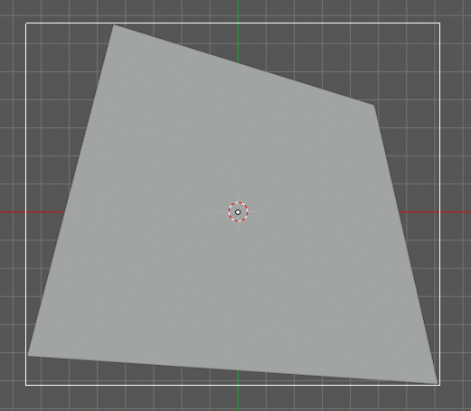
The following is the unit square (which is used for Quads when Coordinates is set to As Is):
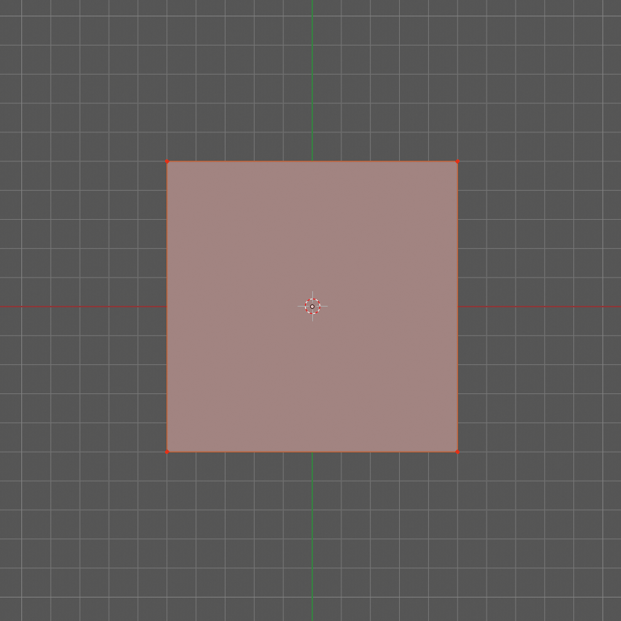
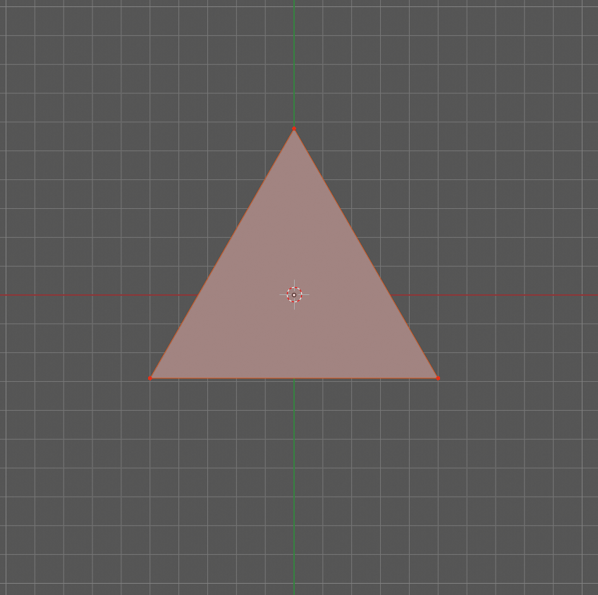
The following illustration demonstrates the meaning of term “bounding equilateral triangle” (it is used for Tris when Coordinates is set to Bounds, and Bounding triangle is set to Equilateral):
The following is the unit equilateral triangle (it is used for Tris when Coordinates is set to As Is, and Bounding triangle is set to Equilateral):
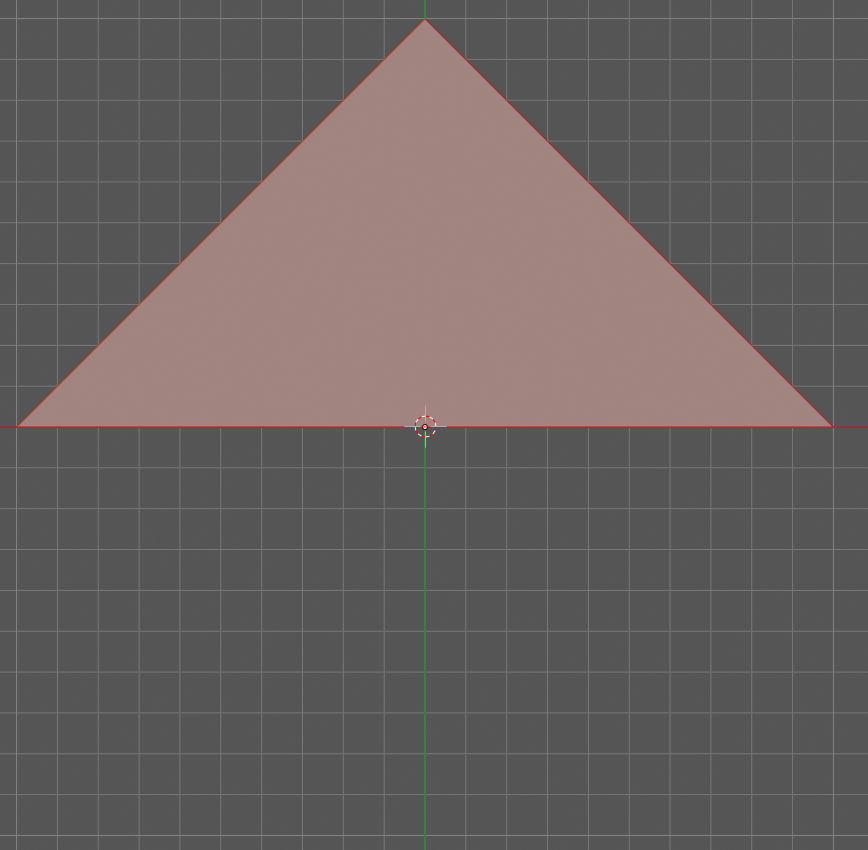
The following demonstrates the meaning of term “bounding rectangular triangle” (it is used for Tris when Coordinates is set to Bounds, and Bounding triangle is set to Rectangular):
The following is a “unit rectangular triangle” (it is used for Tris when Coordinates is set to As Is, and Bounding triangle is set to Rectangular):
Outputs#
This node has the following outputs:
Vertices
Polygons
FaceData. List of data items, which were provided in the FaceDataD input, containing one data item for each face of output mesh.
VertRecptIdx. For each output vertex, this output contains an index of recipient object face, which was used to construct this output vertex.
FaceRecptIdx. Foreach output face, this output contains an index of recipient object face, which was used to construct this output face.
The outputs will contain one object, if Join flag is checked, or one object per recipient object face, otherwise.
Examples of usage#
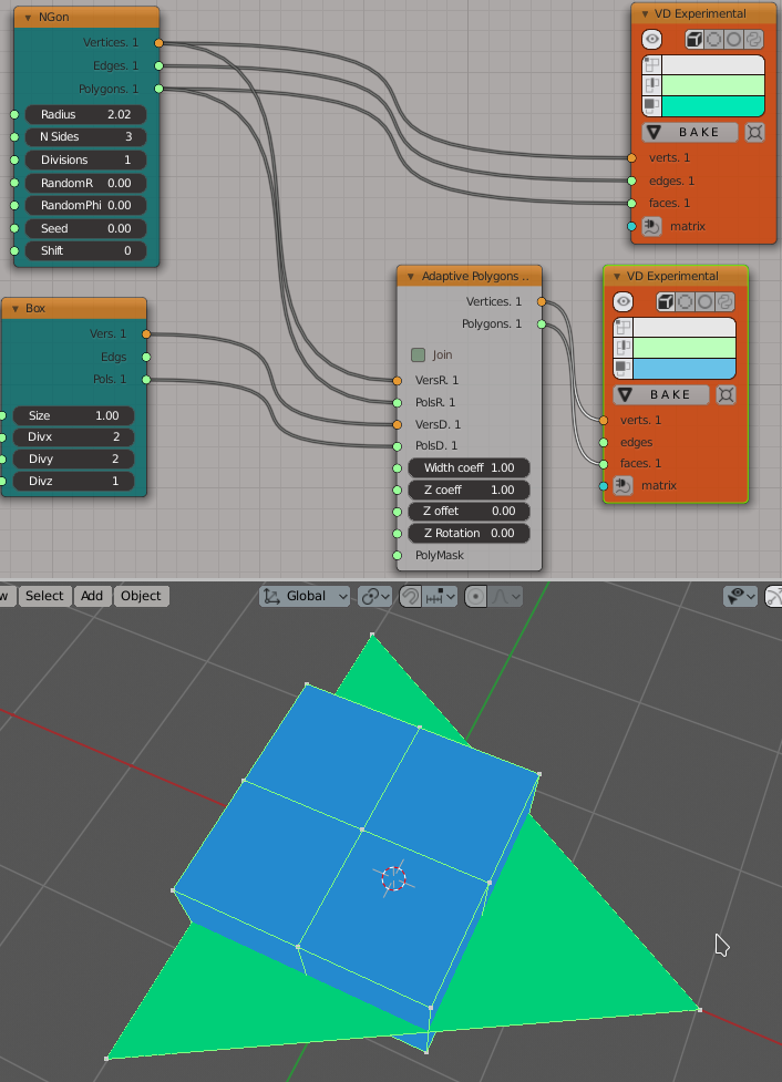
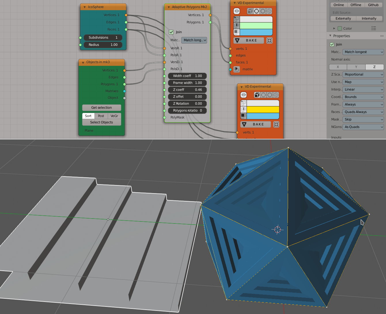
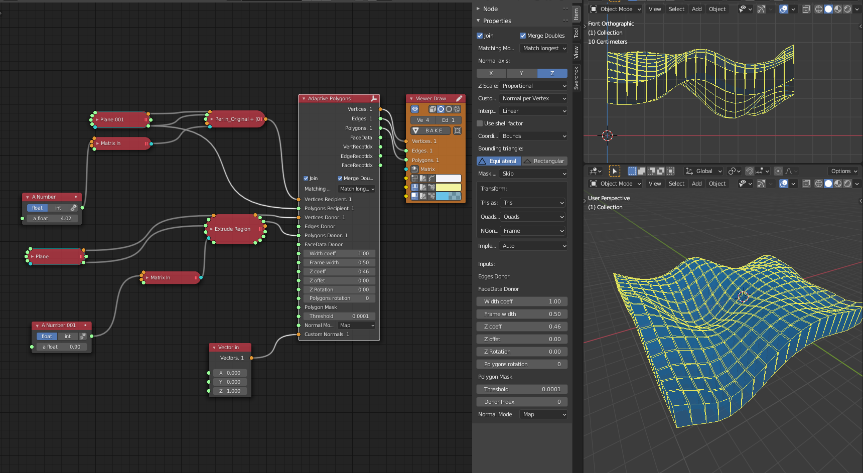
Example of Z coeff input usage:
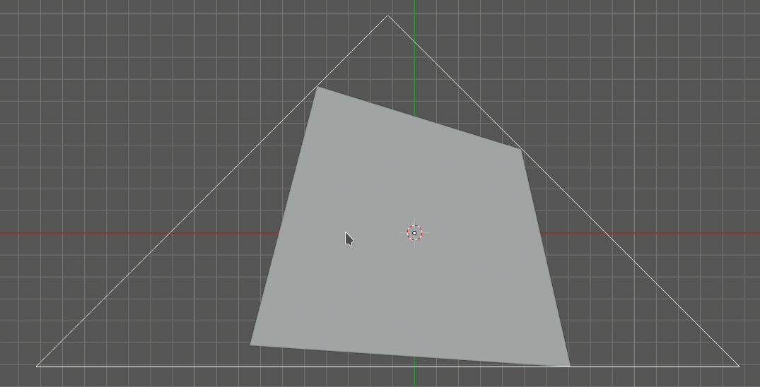
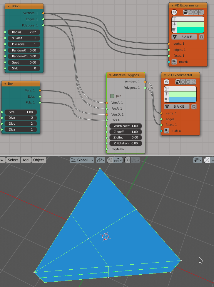
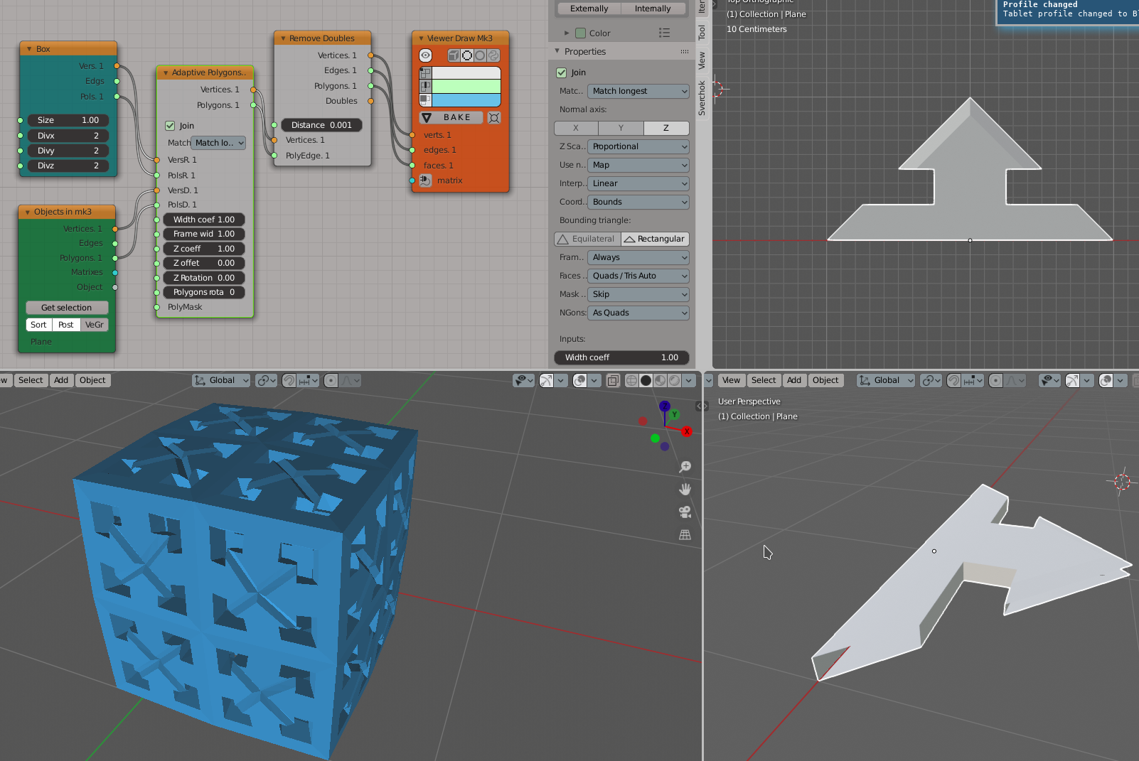
Demonstration of how this node works with Tris recipient faces by default (in Quads / Tris Auto mode):
The same setup but with Faces mode set to Quads Always:
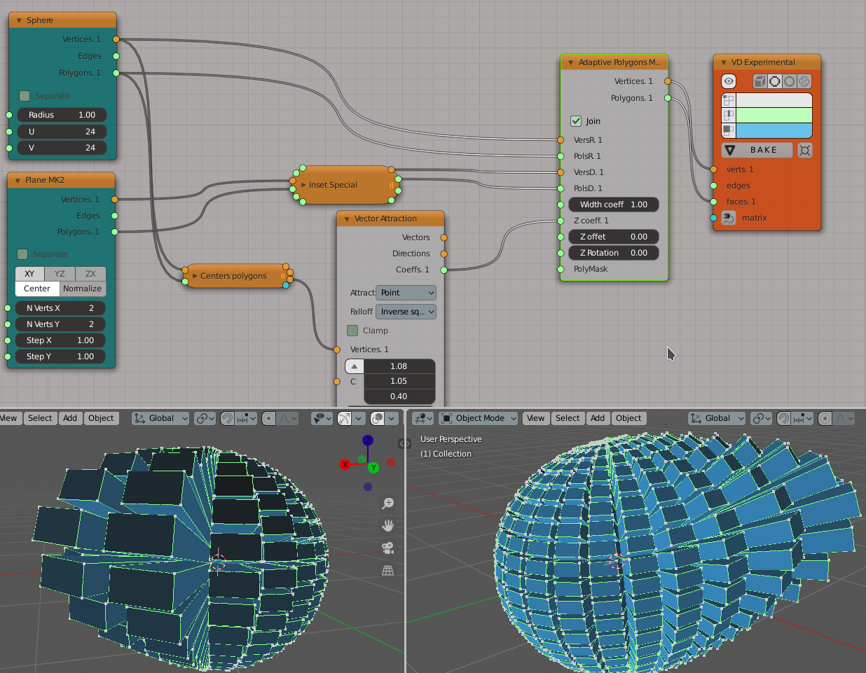
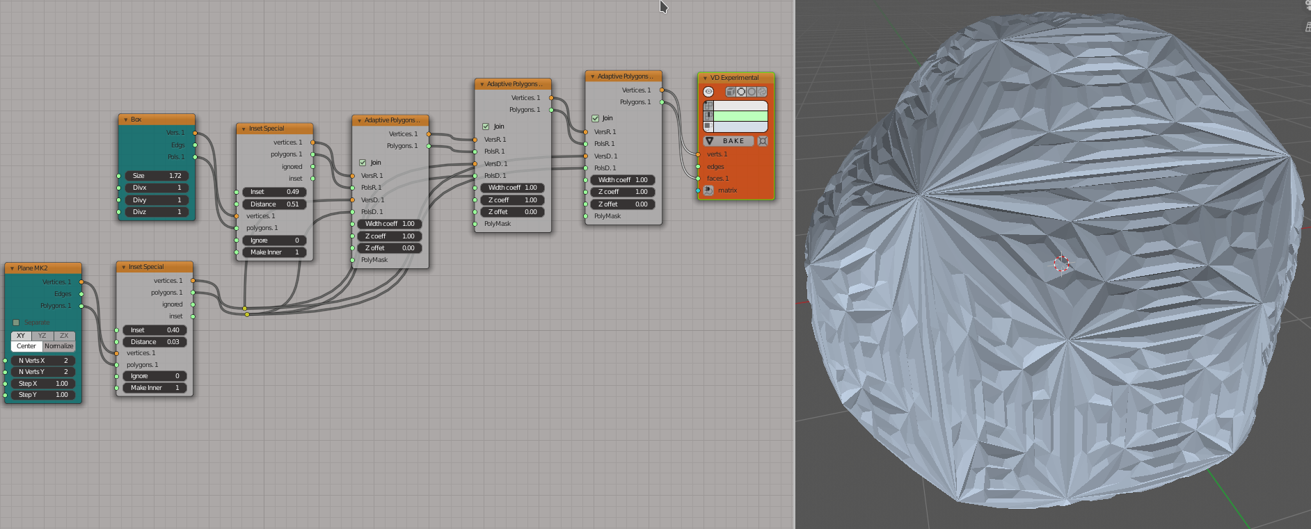
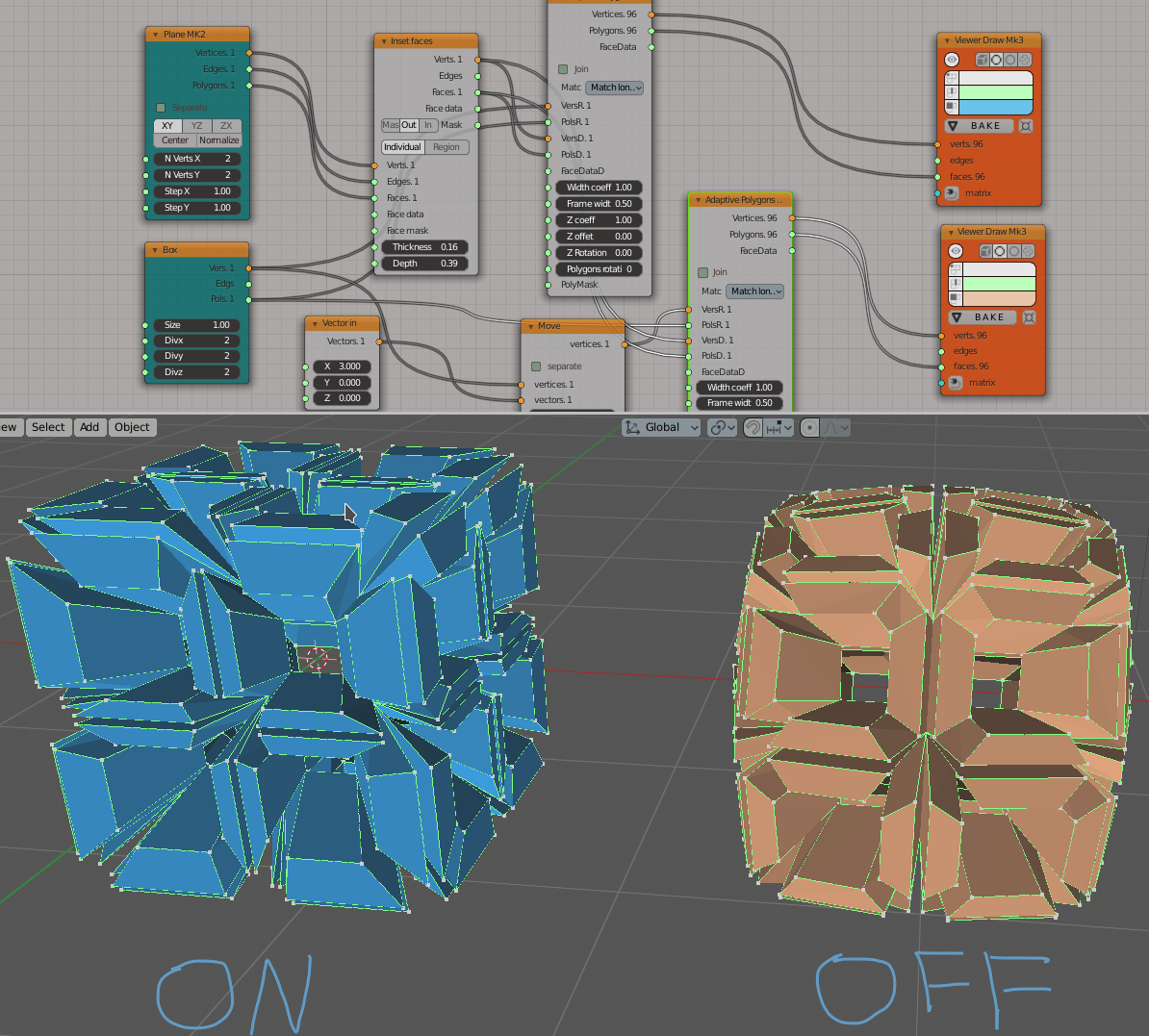
In some cases iterative application can give interesting results:
An example of Frame mode:
The same setup with FrameWidth set to 1.0 - the processing switches to Fan mode:
An example of Rectangular triangles usage:
An example of “Use shell factor” parameter usage:
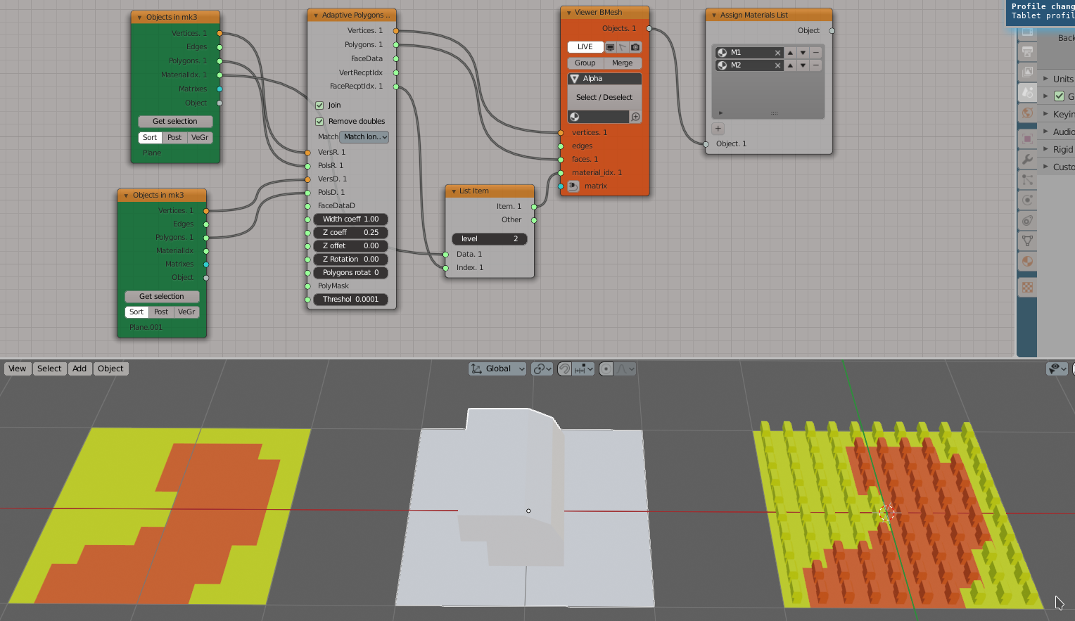
Use materials from the recipient object faces for the resulting object:
Using custom normals to control the z axis of the donors:
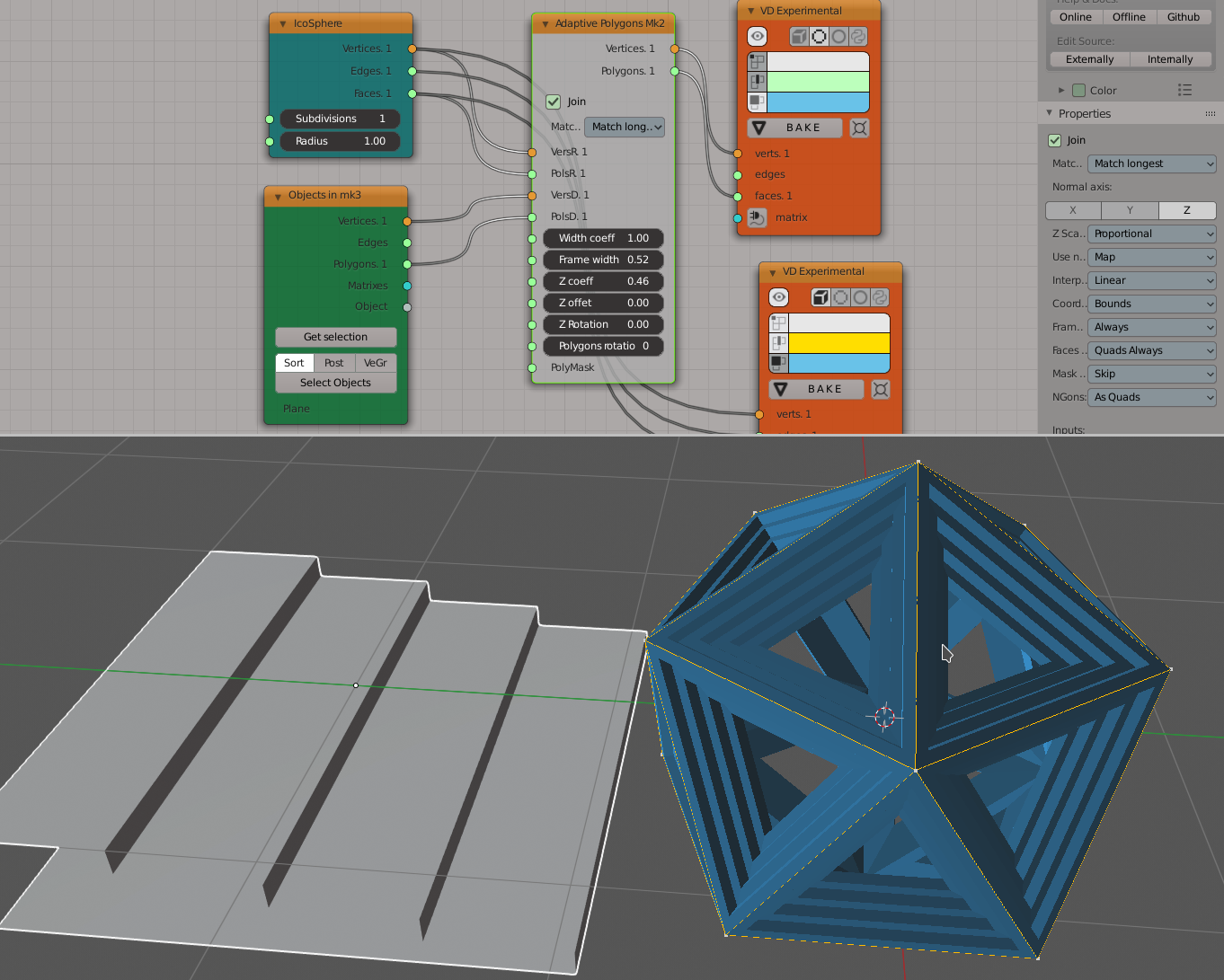
Using edges to create adaptive curves:
You can also find some more examples in the development thread 1 and in the development thread 2.